КАТЕГОРИИ:
Архитектура-(3434)Астрономия-(809)Биология-(7483)Биотехнологии-(1457)Военное дело-(14632)Высокие технологии-(1363)География-(913)Геология-(1438)Государство-(451)Демография-(1065)Дом-(47672)Журналистика и СМИ-(912)Изобретательство-(14524)Иностранные языки-(4268)Информатика-(17799)Искусство-(1338)История-(13644)Компьютеры-(11121)Косметика-(55)Кулинария-(373)Культура-(8427)Лингвистика-(374)Литература-(1642)Маркетинг-(23702)Математика-(16968)Машиностроение-(1700)Медицина-(12668)Менеджмент-(24684)Механика-(15423)Науковедение-(506)Образование-(11852)Охрана труда-(3308)Педагогика-(5571)Полиграфия-(1312)Политика-(7869)Право-(5454)Приборостроение-(1369)Программирование-(2801)Производство-(97182)Промышленность-(8706)Психология-(18388)Религия-(3217)Связь-(10668)Сельское хозяйство-(299)Социология-(6455)Спорт-(42831)Строительство-(4793)Торговля-(5050)Транспорт-(2929)Туризм-(1568)Физика-(3942)Философия-(17015)Финансы-(26596)Химия-(22929)Экология-(12095)Экономика-(9961)Электроника-(8441)Электротехника-(4623)Энергетика-(12629)Юриспруденция-(1492)Ядерная техника-(1748)
Crankcase Splitting. • Turn the engine over so it is upright
|
|
|
|
|
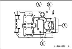
• Turn the engine over so it is upright.
• Put the 8 mm bolts [A], and the 6 mm bolts [B] into the upper crankcase half as shown in the figure, torque the 8 mm bolt first, then the other bolts in the sequence shown.
Torque - Crankcase 8 mm Bolts: 27 N-m (2.8 kgf-m, 20 ft-lb) Crankcase 6 mm Bolts: 12 N-m (1.2 kgf-m, 104 in-lb)
• After tightening all crankcase bolts, check the following
items:
ODrive shaft and output shaft turn freely.
OWhile spinning the output shaft, gears shift smoothly from
the 1st to 6th gear, and 6th to 1st. OWhen the output shaft stays still, the gear can not be
shifted to 2nd gear or other higher gear positions.
9-14 CRANKSHAFT/TRANSMISSION
Clutch Housing/Primary Chain
Clutch Housing/Primary Chain Removal
• Remove the engine.
• Remove:
Cylinder Head, Cylinder and Pistons (see Cylinder Head, Cylinder and Piston in the Engine Top End chapter)
Starter Clutch Sprocket (see Starter Clutch Sprocket Removal in the Electrical System chapter) Clutch (except the Clutch Housing)
• Split the crankcase.
• Lift up the transmission drive shaft assembly [A], and pull the shaft out of the clutch housing [B].
| * | ||||
| to* | I9P | -1 1 | ||
| ' М-°Д | ||||
| №3 | ||||
| з | ^B | "^шми с |
|
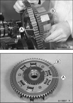
• Place the clutch housing on the balancer drive gear, slack off the primary chain [A] as much as possible and slip the primary chain off the clutch housing sprocket [B].
• Remove the clutch housing [A].
• Pull off the oil pump drive gear [B] from the clutch housing. Lift up the crankshaft, and remove the primary chain.
Clutch Housing/Primary Chain Installation
• Install the primary chain on the sprocket of the crankshaft.
• Install the oil pump drive gear fitting its pin [A] to the groove [B] of the clutch housing sprocket.
| Ф | ®t | |
| 1^ | 3 4& 1 * Л - | m ЦшЦ ■■пака г |
CRANKSHAFT/TRANSMISSION 9-15
Clutch Housing/Primary Chain
• Install the spacer [A] onto the drive shaft [B], facing the chamfered side [C] to the ball bearing [D]. Install the clutch housing in the reverse order of removal.
| f | |
| Щ.Ф | . fe« |
| ' lUll^™ I^La. | |
| \ \щк$м |
Primary Chain Guide Wear Inspection
• Visually inspect the rubber on the guides.
• If the rubber is cut or damaged in any way, replace the guide.
Torque - Upper/Lower Primary Chain Guide Mounting Bolts: 11 N-m (1.1 kgf-m, 95 in-lb)
9-16 CRANKSHAFT/TRANSMISSION
Crankshaft/Connecting Rods
|
Crankshaft Removal
• Split the crankcase (see Crankcase Splitting).
• Remove the clutch housing and the primary chain.
• Remove the crankshaft with the camshaft chain and primary chain.
| CAUTION |
| If the crankshaft, bearing inserts or crankcase halves are replaced with new ones, select the bearing inserts and check clearance with plastigage before assembling engine to be sure the correct bearing inserts are installed. |
Crankshaft Installation
• Apply molybdenum disulfide oil to the crankshaft bearing inserts.
• Install the camshaft and primary chains on the crankshaft.
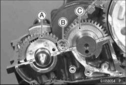
• Align the timing mark [B] on the balancer gear [A] with the timing mark [B] on the balancer drive gear [C] of the crankshaft. Assemble the crankcase (see Crankcase Assembly).
Connecting Rod Removal
• Removethecrankshaft(seeCrankshaftRemoval).
|
|
|
|
|
Дата добавления: 2014-12-23; Просмотров: 438; Нарушение авторских прав?; Мы поможем в написании вашей работы!