КАТЕГОРИИ:
Архитектура-(3434)Астрономия-(809)Биология-(7483)Биотехнологии-(1457)Военное дело-(14632)Высокие технологии-(1363)География-(913)Геология-(1438)Государство-(451)Демография-(1065)Дом-(47672)Журналистика и СМИ-(912)Изобретательство-(14524)Иностранные языки-(4268)Информатика-(17799)Искусство-(1338)История-(13644)Компьютеры-(11121)Косметика-(55)Кулинария-(373)Культура-(8427)Лингвистика-(374)Литература-(1642)Маркетинг-(23702)Математика-(16968)Машиностроение-(1700)Медицина-(12668)Менеджмент-(24684)Механика-(15423)Науковедение-(506)Образование-(11852)Охрана труда-(3308)Педагогика-(5571)Полиграфия-(1312)Политика-(7869)Право-(5454)Приборостроение-(1369)Программирование-(2801)Производство-(97182)Промышленность-(8706)Психология-(18388)Религия-(3217)Связь-(10668)Сельское хозяйство-(299)Социология-(6455)Спорт-(42831)Строительство-(4793)Торговля-(5050)Транспорт-(2929)Туризм-(1568)Физика-(3942)Философия-(17015)Финансы-(26596)Химия-(22929)Экология-(12095)Экономика-(9961)Электроника-(8441)Электротехника-(4623)Энергетика-(12629)Юриспруденция-(1492)Ядерная техника-(1748)
Speed regulation of AM by changing number of pole pairs
|
|
|
|
This method is used for AM with short-circuited rotor, because changing the number of pole pairs in such AM should be provided only on the stator winding, and on the rotor winding – squirrel cage a polarity is set automatically correspondently to polarity of stator winding (polisynchronism). It is not rational to use this method for AM with phase rotor, because the changing of number of pole pairs is necessary on rotor and stator winding, because these windings are identical by construction.
Physical possibility of speed regulation by this method is running out from the sense of angular speed for rotational magnetic field
 ,
,
where  – frequency of supply current of stator;
 – number of pole pairs.
As seen from the formula, the speed can be regulated by changing the number of pole pairs and such regulation can be only gradual, because р=1, 2, 3... - is integer number.
At that, it is possible to obtain only limited quantity of fixed speeds, because its increasing would lead to complication of speed switcher construction or deterioration of using the active materials of motor.
So there are two ways for changing the number of pole pairs.
1 way. Several windings for various number р are situated on the stator, which in turn are switched on the necessary speed. It is not rational to choose more than two windings situated on stator according to thinking of active materials using.
2 way. The only one winding situated on the stator is equipped with the switcher, that provides winding switching for the various number р. It is not rational to choose more than two fixed speeds according to thinking of bulky and complicated construction eliminating.
According to this such multi-speed AM are designed:
- two-speed AM, has one pole-switching winding on stator;
- three-speed AM, has one pole-switching winding and one winding for fixed number of pole pairs on stator;
- four-speed AM, has two pole-switching windings on stator.
But the most of multi-speed AM are two-speed ones.
In pole-switching windings transition from the scheme with the greater р to scheme with the lesser р is possible both at parallel and at series switching of two same parts of windings in each phase.
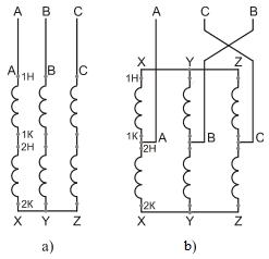
Let’s consider this on example of simplified stator winding, which has two same halves, composed of one turn (i.e. of two conductors). In other words, the stator winding in simplified view has two sections:
1-st section with indications of beginning and end 1Н – 1К;
2-nd section with indications of beginning and end 2Н – 2К.
On fragment а of figure 4.27 the scheme of two sections connection into phase, the current of which creates the system with four poles ( ) is shown. On fragment b the scheme of phase with two poles (
 ) at series connection of sections is shown, and on fragment c – with two poles () at parallel winding connection.
In last two cases a number р was decreased twofold, i.e. the field speed was increased twofold.
|
|
|
Let’s define the admissible power of AM for three abovementioned windings connections, if the admissible current of section

remains constant at scheme switching.
Scheme of fragment а on figure 4.27 ()
 .
.
Scheme of fragment b on figure 4.27 ()
 .
.
Scheme of fragment c on figure 4.27 ()
 .
.
In such a way, admissible power for  (scheme a) and for (scheme b) remains constant – the same voltage and the same admissible current, because the intersection of wires, where the current flows, remains the same for scheme a as well as for scheme b.
In scheme c the admissible power increases twofold, because the voltage remains constant before and after the switching, and admissible current can be increased twofold, because the intersection of wires, where the current flows, is increased twofold.
Admissible moment for all three cases is defined by the formula
 .
.
With this it should be considered that accepting the speed for as w1, the speed for will be 2w1.
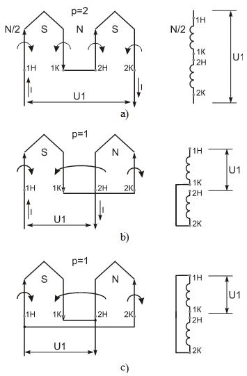
а – four-pole system;
b – two-pole system at series connection of sections;
c – two-pole system at parallel connection of sections.
Figure 4.27 – Schemes of transition into lesser number of pole pairs of pole-switching windings AM.
Then finally:
,
 (scheme а);
,
 (scheme b);
,
 (scheme c).
In such a way, admissible moments of motor for and for from scheme b – are various. At transition to the high speed it is decreased twofold. And admissible moment of motor for and for from scheme c is the same. I.e. at transition from the lower speed to the higher one in this case the admissible moment doesn’t change.
Abovementioned schemes of stator winding are taken for the one phase.
The most widely used three-phase schemes of stator winding at switching to the various p are the following.
The transition from to with the constant power (moment decreases twofold) is realized by such connection schemes of phase windings:
wye - wye (Y/Y), figure 4.28;
delta – double wye (Δ/YY), figure 4.29.
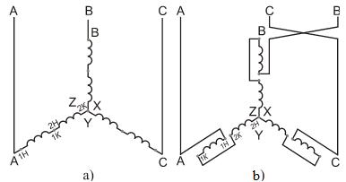
а – wye (Y),;
b – wye (Y),.
Figure 4.28 – Scheme for series switching of windings.
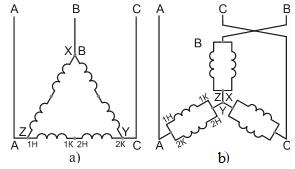
а – delta (Δ),;
b – double wye (YY),.
Figure 4.29 – Scheme for parallel switching of windings.
In scheme, figure 4.28, transition from agreeable-series connection of sections (1Н – 1К, 2Н – 2К) in phases of wye (fragment a) to anti-series connection (1Н – 1К, 2К – 2Н) in phases of wye (fragment b) is realized in accordance to schemes of figure 4.27 (fragments а and b).
In scheme, figure 4.29, transition from agreeable-series connection of sections (1Н – 1К, 2Н – 2К) in phases of delta (fragment а) to anti-parallel connection (1Н, 2К – 1К, 2Н) in phases of double wye (fragment b) is realized in accordance to schemes of figure 4.27 (fragments а and c).
Mechanical characteristics of two-speed AM for schemes of figure 4.28 (Y/Y) and figure 4.29 (Δ/YY) under conditions of speed regulation with constant power
 ,
,

are represented on figure 4.30.
Figure 4.30 – Mechanical characteristics of two-speed AM for schemes Y/Y and Δ/YY.
The transition from to with the constant admissible moment (power increases twofold) is realized, for example, according to schemes of phase winding connections Y/YY, figure 4.31.
|
|
|
In scheme, figure 4.31, transition from agreeable-series connection of sections (1Н – 1К, 2Н – 2К) in phases of wye (fragment а) to anti-parallel connection (1Н, 2К – 1К, 2Н) in phases of double wye (fragment б) is realized in accordance to schemes of figure 4.27 (fragments а and c).
а – wye (Y),;
b – double wye (YY),.
Figure 4.31 – Scheme for parallel switching of windings.
Mechanical characteristics of two-speed AM for schemes of figure 4.31 (Y/YY) under the conditions of speed regulation with the constant moment
 ,
,

are represented on figure 4.32.
Scheme YY on figures 4.29 and 4.31 is represented in various views. It is executed with purpose to acquaint a reader with different methods of schemes graphical markings.
In schemes of figures 4.28, 4.29 and 4.31 at transition to lesser number of poles sequence of phases is changed (from А-В-С to А-С-В) in the winding, with the purpose to remain sequence as constant, i.e. А-В-С, at powering to maintain the direction of rotation at transition from lower speed to higher.
The explanation of this process is such.
Figure 4.32 – Mechanical characteristics of two-speed AM for schemes Y/YY.

а – the phase zone angle of stator winding 120 electrical degrees;
b - the phase zone angle of stator winding 60 electrical degrees.
Figure 4.33 – The wyes of concentrated values for stator phase voltages of AM.
On figures 4.28, 4.29 and 4.31 at transition from the first connection scheme of stator windings phases to second one, in the stator winding the angle of phase zone is changing from 120° (fragment а of figure 4.33) to 60° (fragment b).
From the abovementioned multi-speed AM the greatest range of regulation can be  or
or  , for example, for four-speed AM the relationship of synchronous rotation frequencies can be,
  :
:
- range (3000/1500/750/375);
- range (3000/1500/1000/500).
|
|
|
|
|
Дата добавления: 2014-01-05; Просмотров: 590; Нарушение авторских прав?; Мы поможем в написании вашей работы!