КАТЕГОРИИ:
Архитектура-(3434)Астрономия-(809)Биология-(7483)Биотехнологии-(1457)Военное дело-(14632)Высокие технологии-(1363)География-(913)Геология-(1438)Государство-(451)Демография-(1065)Дом-(47672)Журналистика и СМИ-(912)Изобретательство-(14524)Иностранные языки-(4268)Информатика-(17799)Искусство-(1338)История-(13644)Компьютеры-(11121)Косметика-(55)Кулинария-(373)Культура-(8427)Лингвистика-(374)Литература-(1642)Маркетинг-(23702)Математика-(16968)Машиностроение-(1700)Медицина-(12668)Менеджмент-(24684)Механика-(15423)Науковедение-(506)Образование-(11852)Охрана труда-(3308)Педагогика-(5571)Полиграфия-(1312)Политика-(7869)Право-(5454)Приборостроение-(1369)Программирование-(2801)Производство-(97182)Промышленность-(8706)Психология-(18388)Религия-(3217)Связь-(10668)Сельское хозяйство-(299)Социология-(6455)Спорт-(42831)Строительство-(4793)Торговля-(5050)Транспорт-(2929)Туризм-(1568)Физика-(3942)Философия-(17015)Финансы-(26596)Химия-(22929)Экология-(12095)Экономика-(9961)Электроника-(8441)Электротехника-(4623)Энергетика-(12629)Юриспруденция-(1492)Ядерная техника-(1748)
DCM starting control in time function
|
|
|
|
From starting diagram  and
and , (figure 7.7) it is seen that shunting of starting resistors step must be realized through certain time intervals:
  ,
,  and
and  , i.e. the 1st resistor step should be shunted after ,after – the second, and after– the third. The ability of design of starting control scheme at a function of time is determined by that.
For this purpose different current relays are used, which are set for specified time intervals. Electromechanical and electronics relays are of the most wide application.
Required hold time of every relay is determined on a base of starting diagram. For this it should to subtract own time of contactor energizing from starting time:
 s – DC contactors;
 s – AC contactors.
Time relays control accelerating contactors after hold time expiring independently from current passing through the motor and speed that armature is accelerated to, respective step of starting resistor is shunted.
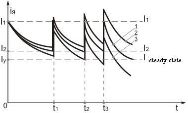
Figure 7.12 – Three-step starting diagram for armature current at load changing at starting.
At these conditions if the motor at starting was overload then the starting process will be realized in accordance with curve 2, and if the motor at starting moment was underloaded then starting process will be realized in accordance to curve 3.
According to the 1st curve:
- average starting moment will increase and starting time remains constant (curve 2);
- average starting moment will decrease at constant starting time (curve 3).
In order to that at equal load the starting moment remains equal to calculated it should respectively change the relay hold time that would meet the requirements of change in load.
So if the starting is realized in accordance to curve 2 (overloading) the hold time will be
 ;
;
 ;
;
 .
.
If the starting is realized in accordance to curve 3 (underloading), then
 ;
;
 ;
;
 .
.
Advantage of such schemes is absence of danger of some prolonged motor operation at incomplete angular velocity (doesn`t “jammed” at any step of starting resistor), that we can`t manage to avoid at scheme of control in speed and current functions.
Danger, which can appear at sudden abrupt increasing of the load at starting because of any internal or external reasons, is eliminated by the presence of maximal protection y the help of which the motor is deenergized from the main.
Simplicity and reliability in operation, and also ability of application time relays of the same types at multistep starting result to the wide application of the method of controlling by starting in time function.
In DC EDs electromagnetic time relays, rather simple and reliable in operation are applied.
For such time relays at two-step starting of DCM the scheme has the next view.
The scheme has two time relays KT1 and KT2, each of which counts the time of changing of angular speed at starting on correspondent resistor stage and turns on correspondent acceleration contactors KM2 and KM3. The command of time counting to each current relay is send by the previous contactor at its turning on:
|
|
|
- to the relay KT1 by contactor KM1;
- to the relay KT2 by contactor KM2;
- to the relay KT3 by contactor KM3(if it would be three resistor stages) and so on;
The scheme operates by the next way. At initial state relay KT1 is closed, it means that its closing contact KT1 is opened, because coils of accelerator contactors KM2 and KM3 are not connected to the supply, and forced contacts of these contactors KM2 and KM3 – are deenergized.
After energizing of linear contactor KM1 (by the button SB2 we switch on the coil of the contactor KM1, contactor KM1 responses, realizing automatic switching by contacts KM1, which shunt the button SB2) the main contact KM1 is turned on in armature circuit and closing contact KM1 in the circuit of the coil of time relay KT1 is opened.
With this armature winding of the motor M is connected to the main through the starting resistor R1-R2 and motor begins to operate. At first current ripple due to voltage drop on resistor R1 relay KT2 is turned on and opens its closing contact KT2 in the circuit of contactor KM3 coil (the second stage of starting resistor R2 remains turned on).
Relay KT1, haven lost the supply at the beginning of start, starts the time counting (which is approximately equal to operation time of the motor at the first stage of R1). After finishing of this time relay KT1 responses and by the help of contact KT1 (in the circuit of the coils of contactors KM2 and KM3) deenergizes the coil of the contactor KM2, which by its forced contacts KM2 in armature circuit of the motor M disconnects the first stage of the resistor R1 and closes short-circuited the coil of time relay KT2. This relay starts the counting of holding time, which is equal to operation time of the motor M on the second stage of starting resistor R2. After finishing of this time its contact KT2 is closed (in the circuit of the coil of contactor KM3) and forced contacts KM3 which disconnect (shunt) the second stage of resistor R2 are deenergized.
Advantage of control moment at the starting of the motor in time function is the constancy of starting time at changing of external effects:
- resistive moment;
- inertia moment;
- supply voltage;
- environment temperature and so on.
For example, when resistive static moment Ms is changed, motor changes the value of switching moments M1 and M2, preserving the time of speed changing almost invariable.
If Ms is increased from Msa to Msb, then switching moment is increased correspondingly from M2 to M′2 and from M1 to M′1 too (if resistance of the firs stage is disconnected), i. e. point a is displaced into a′, and point b into b′. It is happened because at the increasing of resistive moment from Msa to Msb the motor speed during the time (constant), counting by relay KT1 is increased not to the value ω1, but to the value ω′1, and ω′1< ω1. On the next stages switching moments are increased much more. So at the second stage:
 , and
, and ,
,
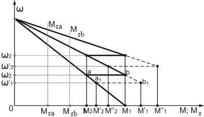
and common starting time almost will not change (holding time of relay KT2 will not be changed and so on).
Disadvantage of starting control in time function is ability of significant increasing of motor currents and moments at increasing of Ms, I, Us and decreasing of τºenv. comparatively with its calculated values.
|
|
|
Since with increasing of Ms acceleration process at the first stage is slowed down, then to the moment of holding time finishing of time relay KT1 the motor speed doesn`t reach calculated speed value (ω1). And after response of the first acceleration contactor KM2 undesirable current and moment ripple will occur, which can exceed admissible values. Pretriggering of the contactor KM2 will force the second time relay KT2 also to start untimely time counting, which will result to pretriggering of the second acceleration contactor KM3 and also to great current and moment ripple and so on. The same situation will be at changing of the second parameters (I, Us …).
|
|
|
|
|
Дата добавления: 2014-01-05; Просмотров: 416; Нарушение авторских прав?; Мы поможем в написании вашей работы!