КАТЕГОРИИ:
Архитектура-(3434)Астрономия-(809)Биология-(7483)Биотехнологии-(1457)Военное дело-(14632)Высокие технологии-(1363)География-(913)Геология-(1438)Государство-(451)Демография-(1065)Дом-(47672)Журналистика и СМИ-(912)Изобретательство-(14524)Иностранные языки-(4268)Информатика-(17799)Искусство-(1338)История-(13644)Компьютеры-(11121)Косметика-(55)Кулинария-(373)Культура-(8427)Лингвистика-(374)Литература-(1642)Маркетинг-(23702)Математика-(16968)Машиностроение-(1700)Медицина-(12668)Менеджмент-(24684)Механика-(15423)Науковедение-(506)Образование-(11852)Охрана труда-(3308)Педагогика-(5571)Полиграфия-(1312)Политика-(7869)Право-(5454)Приборостроение-(1369)Программирование-(2801)Производство-(97182)Промышленность-(8706)Психология-(18388)Религия-(3217)Связь-(10668)Сельское хозяйство-(299)Социология-(6455)Спорт-(42831)Строительство-(4793)Торговля-(5050)Транспорт-(2929)Туризм-(1568)Физика-(3942)Философия-(17015)Финансы-(26596)Химия-(22929)Экология-(12095)Экономика-(9961)Электроника-(8441)Электротехника-(4623)Энергетика-(12629)Юриспруденция-(1492)Ядерная техника-(1748)
Action -Table 1 страница
|
|
|
|
F014ACTION- Table P04
U> o =+=
oo a)
coo -+
""""'':::::!: (./}
<D 0 0
|
::J (/)
O 'T\0
 T1 = =====J F13N1 lnp.del-1
(f) c6" F13N2 T.counter-1
110·021·01
F14PN1 Startup-1
F14PN2 Startup-2
..... 0.....
..... <D
 c L...........,
13N3 lnpd.el-2
o.::---a
;v (i)
F
F13N4 T.counter-2
11-002-102
F14PN3 Startup-3
F14PN4 Startup-4
<D j:>.,
 o _,co
() F13N5 lnp.del-3
0 '. E.. F13N6 T.counter-3
11-002-103
F14PN5 Startup-S
F14PN6 Startup-6
-0= O,.- U.. >..
::£ o s·
---<
F13N7 lnp.del-4
11-002-104
F14PN7 Startup-7
-::J-: :€ v
|
F14PNB Startup-S
,,....::J c
|
rz
;A;
F13N9 lnp.def-5
F13N10 T.counter-5
 "D 0100010100... F13N11 lnp.def-6
11-002-105
11-002-106
F14PN9 Act-1 109-001-001 1: INP1· Alt.green to Gl with ownmaM
F14PN10 Act-2 109-002-002 2: INP2: All.g<een to G2 wtih ownrna< F14PN11 Act-3 109-003-003 3: INPJ All.green to G3 with ownmaM
-+ '-../
::r s·-·
<D "D::J
U> c-+
OJ Q F13N12 T.counter-6
m::J F13N13 lnp.def-7
"D F13N14 T.counter-7
F14PN12 Act-4 109-004-004 4: INP4· Alt.green to G4 with ownmaM
F14PN13 Act·5 109-005-005 5: INP5: Alt.green to G5 with ownmaM
F14PN14 Act-6 109-006-006 6: INP6·All.g1eentoG6 withownmalo!
0 -+-:::J"
Q. <D
::£ <D 0
mm 0 F13N15
z co
lnp.def·B
F14PN15 Act7·
111 001 011 7: INP11: RedloGl wilhown va1. p·e·g
0::::h 0
|
|
F13N17 lnp.def-9
3 F13N1B T.counter-9
0 3 F13N19 lnp.def·10
)> s· F13N20 T.counter-10
z co F13N21 lnp.def11
|
0 2 F13N23 lnp.def-12
|
-+ F13N25 lnp.def-13
11·003-101 $
11·0031· 02
11·003-103
F14PN16 Act·B 111·002 012 8: INP12: Red to G2 with own va<.p·eg· F14PN17 Acl-9 111-003-013 9: INP13: Red to G3 with own va1. p·e·g F14PN1B Act·10 111·004·014 10: 1NP14: R ed lo G 4 wilh ownval.p·e·g F14PN19 Act·11 111-005·015 11: tNP15: Red to G5withown vaLp·e·Q F14PN20 Act-12 111·0060· 16 12: 1NP16: R edlo G6wihl own val.p·e·g F14PN21 Act·13 13:
F14PN22 Act-14 14
F14PN23 Act-15 15: F14PN24 Act-16 16
<D::;:-+
|
CO U><D
|
(/) T1 <
o <D
-c.;; Q
 m c
m c
;v (i) F13N26 T.counter-13
F13N27 lnp.def-14
F13N2B T.counter-14
F13N29 lnp.def-15
F13N30 T.counter-15
F13N31 lnp.def-16
IJ
co
<0
()-..
s_
;s
11·003·104
11·0031·05
11-003-106
9,s·
 c 0
c 0
::J 0
<D
::J.
_,_,
::y::Y
<D <D
0 0
0 0
|
0·-.....
::JQ_
U>{i)
Q'
0 <D
<D I'
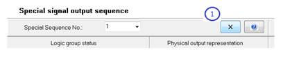
10 Special signal group sequence programming
When programming special signal group sequence, choose one from 8 available special se- quences from the list (1) and press the edit button (2).
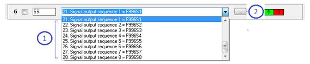
Figure 195: Signal group type list
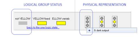
The left side of the table represent logical group status (1) and the right side represent physical group status (1). As a default all signal groups remain dark in all logical statuses. Here you have to decide what should be the real physical representation for each logical status.
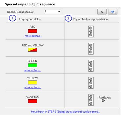
Figure 196: Special signal group sequence programming panel
For example: you can make signal group physically yellow flashing while it is logical green..
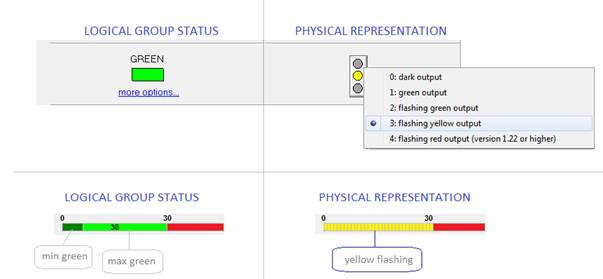
Figure 197: Flashing yellow
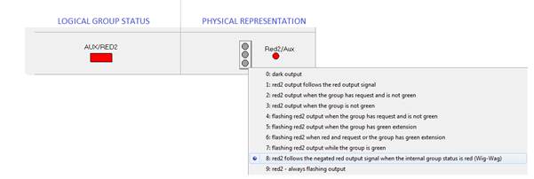
In order to use more options and distinguish physical representations for a different green or red logical statuses press the ”more option” link (1).
For example: in min green and passive green signal group will remain green but in p-e-g green group will be flashing red.
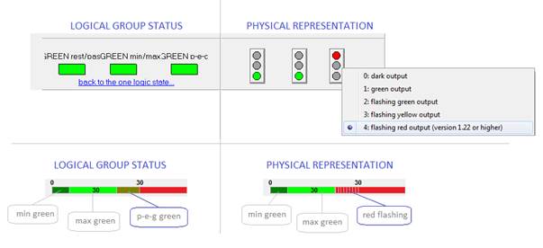
Figure 198: More options
When programming special yellow output sequence it is very important to set ”DARK” physical representation for ”NOT YELLOW” logical state.
Wig-Wag red flashing is a specific sequence when the main red output flash in opposite to
Aux/Red2.
Press the ”close” button (1) in order to get back to the signal group min sequence program- ming (STEP 2).
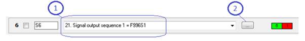
For group S6 use the Special Sequence 1(1). You can always press the ”edit” button (2) again in order to check what is the real physical representation for the logical group status.
11 Additional intergreen time matrix programming
It is possible to use 4 additional intergreen time matrix tables. First Enable additional tables in STEP 1 - Control options page
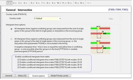
Figure 199: Enabling additional intergreen time matrix
Now, you will find 4 additional intergreen time matrix in STEP 8. The first matrix is a base one (1) and all other 4 are additional (2). You can add logical conflicts here or make the value bigger for the specific conflicts.
At first all additional matrix tables remain disabled - as there is no enabling input defined yet. Click on the ”INPUT definition button” (3) in order to define the moment when the additional matrix grid should become enabled.
To learn more about different types of enabling inputs see: Other input types section 5.2.12, page 79
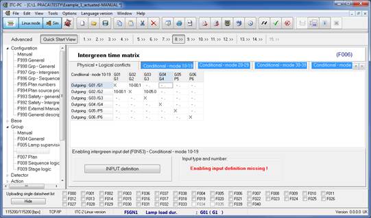
Figure 200: Additional intergreen time matrix’s
The first two conflict value digits represent intergreen time mode and only the next 3 represent time in [s].
- base matrix - mode = 00 - 06,
- first additional matrix = mode = 10 - 16
- second additional matrix = mode = 20 - 26
- third additional matrix = mode = 30 - 36
- forth additional matrix = mode = 40 - 46
Default modes are set automatically.
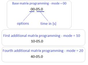
Figure 201: Intergreen time modes and time
Each additional matrix grid remains disabled as long as the associated enabling input stays inactive. Additional conflicts becomes enabled only while its enabling inputs change to active state.
For example: additional matrix grid 1 becomes enabled only when current plan number = 2.
To learn more about different type of enabling inputs see: Other input types section 5.2.12, page 79
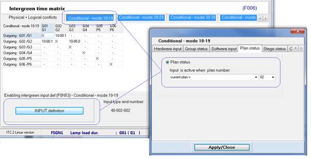
Figure 202: Enabling input definition
12 Action Table programming
The Action Table contains different type of actions that can influence your base programming. For example, you can force some specific signal group to red or disable/enable detector requests in other signal group.
In order to use actions, first associate plan with a specific Action Table - usually Action Table number = Plan number.
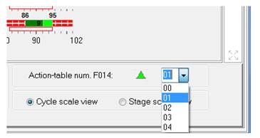
Figure 203: Action Table number
For the plans with the Action Table number associated, the create action function becomes enabled. Click on the ”Create Action” function from the menu and choose the action type.
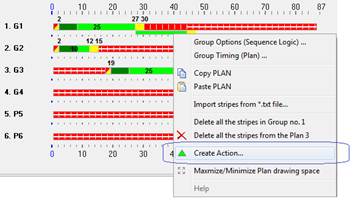
Figure 204: Create action menu
There is a list of different Actions that can be used in order to influence your base programming. Each action can be activated in a specific cycle point - Cycle counter action type (1).
Or when specific input becomes active - Input definition action type (2).
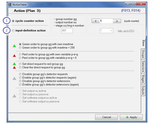
Figure 205: Action types
For example: to force G1 to red in second 40 check the cycle counter action type box (1), set the time in second in the edit field (2), chose the red order action type (3) and press the
”Apply” button.
Action will be presented on the plan drawing picture as a red triangle (4).
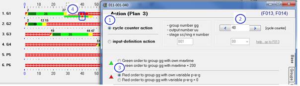
Figure 206: Action plan icon
You can delete your actions at any time. Click the right mouse button on the action icon and choose ”delete” function from the menu.
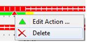
Figure 207: Deleting actions
13 APPENDIX I - Uploading/Downloading
There are two different interfaces you can use to upload/download configuration to the ITC
controller from ITC-PC software tool:
• Ethernet TCP/IP communication,

• Serial communication,
13.1 Ethernet TCP/IP communication
13.1.1 Computer IP address - direct connection
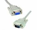
For the LAN direct connection you can check your LAN connection settings to make sure your computer IP belongs to the same area and connect your computer directly to the ITC controller with Ethernet cable.
Open the ”Network and Sharing Center” (Windows 7) - Local Area Network Connection (1).
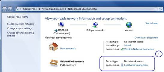
Figure 208: Network and Sharing Center (Windows 7)
Press ”Properties” button (1), check the ”Internet Protocol Version 4 (TCP/IPv4)” item (2) and press the ”Properties” button (3) to check your computer IP.
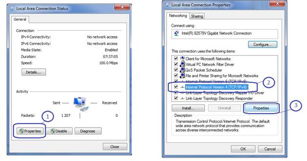
Figure 209: Local Area Connection Status/Properties
For the direct connection make sure your computer IP address belongs to the same IP area as the controller’s IP. For example if the IP address of the ITC controller is 192.168.0.75 your computer IP address could be set to 192.168.0.76.
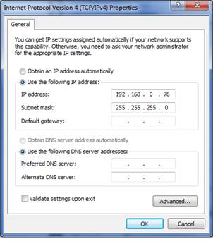
Figure 210: Computer IP address
13.1.2 ITC controller IP address - LAN connection
To connect the ITC controller to your LAN, you would have to check and change the IP address of the ITC controller. You can change your ITC controller IP address and other networking settings from ITC controller web interface - ”System Managment” web site.
Connect your PC with the ITC controller directly with Ethernet cable and type the ITC
controller IP address plus ”:81” port number in your web-browser.
For example ”https://192.168.0.75:81” (default ITC controller IP adddress)(1). Confirm and continue in case of security certificate warnings (2).
Log in to the ITC controller web System Management site (3): User name: admin,
Password: changeME1,

Figure 211: System Management Login
Here, in the ”Networking” tab page (1) you can change the IP address of the ITC controller and other networking stings (2):
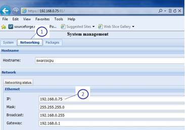
Figure 212: System Management - Networking
For more informations about ITC controller web interface read ”ITC Web Interface” manual.
13.1.3 Checking ITC-PC Ethernet communication settings
The Ethernet communication mode is mostly applicable to ITC-2 Linux version controllers. Make sure you ITC-PC software runs in ITC-2 Linux mode (1):
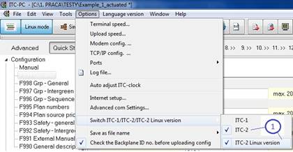
Figure 213: ITC-2 Linux mode
Check the communication port mode and make sure the ITC/PC port is checked (2):
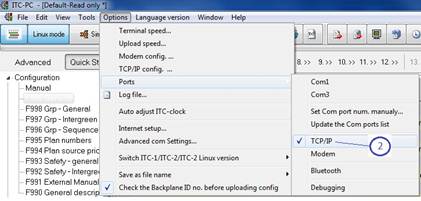
Figure 214: TCP/IP port mode
You can check both modes from the status bar: communication baudrate (default for ITC-2
Linux controller 115200 [bps] (1), communication port (2) and ITC-2 Linux controller mode (3):

Figure 215: TCP/IP port mode
Check the TCP/IP communication mode settings (1). Type the IP address of the controller (2) (default ITC IP address is 192.168.0.75) and the port number (3) (default port number 22/for some older ITC controller versions 3000):

Figure 216: Controller IP and port settings
13.1.4 Uploading configuration to ITC controller
Once both the computer LAN settings and ITC-PC software communication settings are ready, you can start uploading/downloading data to/from the ITC controller.
To upload all data to the ITC controller press Send all data button from tool bar (1) or choose
the ”Send all data” option (2) from the main menu.
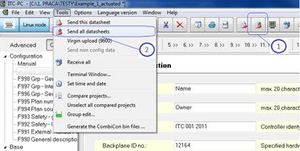
Figure 217: Send all data
Check the ITC controller IP address and port number (1). If it is the first time uploading/down- loading data to/from specific controller before pressing ”Send all data” button (4), first you would have to open the SSH tunnel session (2). It is not necessary to do it for every uploading/- downloading data if the SSH session is already open.
To open the SSH tunnel press the ”Open SSH tunnel” button (2). Opened session will be con- firmed by the black window with the prompt symbol displayed in the third line (3)
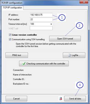
Figure 218: Send all data window

Figure 219: SSH session open
Press ”Send all data” button and ITC-PC software will start sending data to the ITC controller.

Figure 220: Send all data button
Sending the data process is preceded by initiation procedure. The procedure consist of: ITC-PC software authorization (1), ITC controller firmware version check (2), ITC controller BackplaneID number check (3) and Checksum procedure (4):
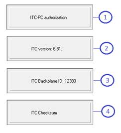
Figure 221: Initiation procedure
After the initiation procedure, ITC-PC software starts sending all the data. Communication status window show you the current sending function number (1) and progress bar (2):
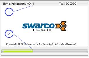
Figure 222: Uploading status window
13.1.5 Downloading configuration from ITC controller
Downloading configuration from ITC controller procedure looks very similar to uploading con- figuration. This time press the Get all data button from tool bar (1) or choose ”Receive all” function (2) from main menu:
Figure 223: Get all data
Check the controller IP address, port number, open the SSH tunnel (if not yet open) and press the ”Get all data” button.

Figure 224: Get all data button
After the initiation procedure ITC-PC software starts receiving all data. The communication status window shows you the current sending function number (1) and progress bar (2):

Figure 225: Downloading status window
13.2 Uploading a single data sheet list
A single data sheet list (1) is a list of functions that will be send once you press ”Send single data sheet” button (2). Press the menu function (3) in order to show/hide the list.
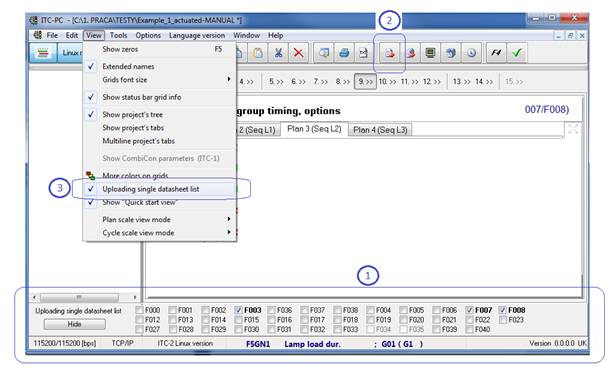
Figure 226: Downloading status window
13.3 Uploading/downloading to/from ITC-Simulator software
It is only possible to upload a single data sheet to the ITC-Simulator or download all data. In order to communicate with the ITC-Simulator press the ”Sim” button (1). The ITC-PC software will be then set in the simulator mode and it will set all necessary communication options auto- matically.
You can now press upload single data sheets to the simulator software or download the whole configuration with using buttons (2).
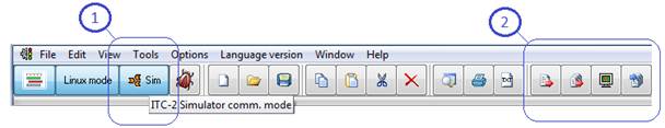
Figure 227: Downloading status window
13.4 Serial communication
It is also possible to use a serial communication to upload/download the configuration. Choose the com port number:
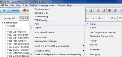
Figure 228: Com port number
Check the serial communication terminal and upload speed:
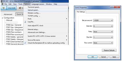
Figure 229: Serial communication settings
You can check current communication settings from the status bar: communication baud rate (default for ITC-2 Linux controller 115200 [bps] (1), communication port (2) and ITC-2 Linux controller mode (3):
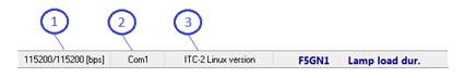
Figure 230: TCP/IP port mode
Connect your computer with the ITC controller with serial cable. Press ”Send all data” or ”Get all data button to upload/download data to/from the controller.
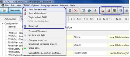
Figure 231: Serial downloading/uploading
After the initiation procedure, the ITC-PC software starts sending/receiving all data. The com- munication status window shows you the current sending function number (1) and progress bar (2):
Figure 232: Uploading/downloading status window
14 APPENDIX II - Main menu
14.1 Main Menu - File
Menu - File contains most important functions (1) for opening, saving creating new ITC con- figuration files (*.PTC, *.PTC2 files). You will also find printing functions (2) and the list of 10 last opened configurations (3).
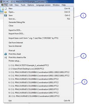
Figure 233: Menu - File
14.1.1 Open new project
To open a new project press the ”New” item. If you want to open an existing project click on
”Open...” item and browse for the configuration file.
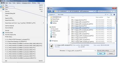
Figure 234: Open new project
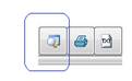
14.1.2 Open new project - tool bar
You can also click on the (New) or (Open) buttons on the main tool bar.

14.2 Main Menu - Edit
Menu - Edit contains some common editing functions such as: Copy, Paste, Cut and Delete
(1). You will also find two additional functions: Activate comment (2) and Find (3).

Figure 235: Edit
You can also click on the (Copy, Paste, Cut or Delete) buttons on the main tool bar.

14.2.1 Activate comment
The activate comment shows some additional informations concerning programming in some of the configuration functions. For example in: F015 Actions, F016 Control Blocks. A comment view can be also activated by pressing the ”F4” button on the tool bar or F4 key.
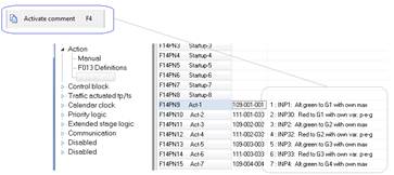
You can also click on the (F4) button on the main tool bar.

14.2.2 Find
The Find function helps you to find any string in the whole ITC configuration. Type string in the edit field (1), press the ”Search” button (2) and software will list all places from the whole configuration where the string was found. Double click on one of the list rows and software will take you to the place in the configuration where the value was found (4).
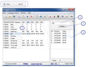
You can also click on the (Find) button on the main tool bar.
14.3 Main Menu - View
Menu -View contains a different software main window viewing options.
14.3.1 Show zeros
The Show zeros fills in all empty parameters with zeros to show the default parameter mask.
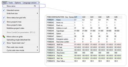
Figure 236: Show zeros
14.3.2 Extended group names
The Extended names option decides about displaying the signal group name in the title table row.
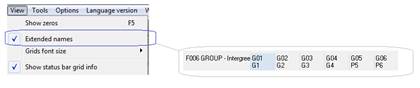
Figure 237: Extended signal group names
14.3.3 Grid font size
There are two grid font sizes available 8 and 10.
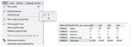
Figure 238: Grid font size
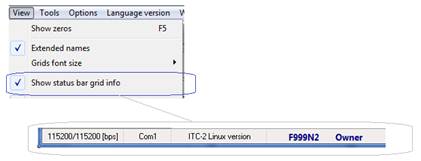
14.3.4 Show status bar
The Show status bar option shows/hides the main ITC-PC software window status bar.
|
|
|
|
|
Дата добавления: 2014-12-23; Просмотров: 1632; Нарушение авторских прав?; Мы поможем в написании вашей работы!