КАТЕГОРИИ:
Архитектура-(3434)Астрономия-(809)Биология-(7483)Биотехнологии-(1457)Военное дело-(14632)Высокие технологии-(1363)География-(913)Геология-(1438)Государство-(451)Демография-(1065)Дом-(47672)Журналистика и СМИ-(912)Изобретательство-(14524)Иностранные языки-(4268)Информатика-(17799)Искусство-(1338)История-(13644)Компьютеры-(11121)Косметика-(55)Кулинария-(373)Культура-(8427)Лингвистика-(374)Литература-(1642)Маркетинг-(23702)Математика-(16968)Машиностроение-(1700)Медицина-(12668)Менеджмент-(24684)Механика-(15423)Науковедение-(506)Образование-(11852)Охрана труда-(3308)Педагогика-(5571)Полиграфия-(1312)Политика-(7869)Право-(5454)Приборостроение-(1369)Программирование-(2801)Производство-(97182)Промышленность-(8706)Психология-(18388)Религия-(3217)Связь-(10668)Сельское хозяйство-(299)Социология-(6455)Спорт-(42831)Строительство-(4793)Торговля-(5050)Транспорт-(2929)Туризм-(1568)Физика-(3942)Философия-(17015)Финансы-(26596)Химия-(22929)Экология-(12095)Экономика-(9961)Электроника-(8441)Электротехника-(4623)Энергетика-(12629)Юриспруденция-(1492)Ядерная техника-(1748)
Transport layer protocol TCP, frame format Protocol TCP
|
|
|
|
Protocol Transport Layer UDP, the aspect ratio of UDP
The protocol UDP (User Datagram Protocol) - is one of the two transport layer protocols that are used in the protocol stack TCP / IP. The task of transport protocol UDP is the transfer of data between application processes with no guarantee of delivery, so its packets can be lost, duplicated, or not come in the order in which they were sent.
The best-known services that are based on UDP, a BIND Domain Name System and Distributed File System NFS. A unit of data called the UDP packet or a UDP-User Datagram (user datagram). UDP-packet consists of header and data fields, which is located a package application layer. UDP-packet format is shown in Figure 5.2.10.
Figure 5.2.10 - Structure of the UDP-packet
The title has a simple format and consists of four two-byte fields:
- Source Port - the port number of the sending process,
- Destination Port - the port of destination,
- Message length - length of the UDP-packet in bytes,
- Checksum - Checksum UDP-packet.
In the Application Data contains the data being transmitted. Not all fields of UDP-packet must be filled. If sent by the datagram does not suggest an answer, then place the sender's address may be placed zeros. You can abandon the checksum.
If an application quality control of data transmission over the network is important, in this case, the protocol TCP is used. TCP is a reliable and connection-oriented protocol. In contrast to the protocol UDP, which delivers the data to a specific port only, and provides no connection, TCP is connection-oriented, i.e. at first establishes a connection.
The reliability of TCP is that the data source repeats its premise, unless it receives a certain amount of time the addressee's acknowledgment of their successful delivery. This mechanism is called Positive acknowledgement with Retransmission (PAR). In TCP header there is the checksum field. If the data is corrupted during it can be determined. Corrupted packet will be destroyed and nothing is sent to the source. If the data are not damaged, they pass on the message assembly applications, and the source of confirmation is sent.
Focusing on the connection from the fact that before sending the data segment, TCP modules source and destination exchange management information. This exchange is called a handshake. TCP uses three-phase handshake:
- Source establishes connection with the recipient by sending a packet with the flag of «synchronizing sequence numbers» (SYN). Number in the sequence determines the packet number in the message application. This does not necessarily have to be either 0 or a unit. But all the other numbers will use it as a base, which will collect the bags in the correct order;
- the recipient meets the number in the receipt of the SYN, which corresponds to the number set by the source. In addition, the «number in the sequence» may also be communicated to a number that prompted for the source;
|
|
|
- a source confirms that the recipient received the segment and sends the first chunk of data.
Graphically, this process is shown in Figure 5.2.11.
Figure 5.2.11 - Setting up the TCP connection
Once the connection source sends data to the receiver and waits for a confirmation of their receipt, then sends the data and so on, until the message ends. Message ends when the flags field is in the exposed bits of FIN, which means “no more data”. Format of the TCP segment is shown in Fig. 5.2.12.
Figure 5.2.12 - Format of the TCP segment
The TCP packets are called segments and consist of a header and data block.
The title segment has the following fields:
- Source port (SOURS PORT) - 2 bytes, identifies the sending process;
- Port of destination (DESTINATION PORT) - 2 bytes, the process of identifying the recipient;
- The sequence number (SEQUENCE NUMBER) - takes 4 bytes indicates the number of bytes that defines the offset of the segment relative to the flow of data being sent;
- Confirmed number (ACKNOWLEDGEMENT NUMBER) - takes 4 bytes contain the maximum number of bytes in the received segment, increased by unity, this value is used as a receipt;
- Header Length (HLEN) - takes 4 bits to indicate the length of the segment header TCP, measured in 32-bit words. The length of the header is not fixed and may vary depending on the values set by the Options field;
- Reserve (RESERVED) - is a 6 bits field is reserved for future use;
- The code bits (CODE BITS) - occupy 6 bits contain proprietary information about the type of the segment defined by setting the corresponding bits in a unit of this field:
- URG - urgent message;
- ACK - received a receipt for the segment;
- PSH - a request to send a message without waiting for the buffer is full;
- RST - a request for reconnection;
- SYN - the message is used to synchronize the counters of data transferred when a connection;
- FIN - a sign of the transmitting side reach the last byte in the stream of data transmitted.
- Window (WINDOW) - 2 bytes contain the value declared by the window size in bytes;
- The checksum (CHECKSUM) - 2 bytes, is calculated for the segment;
- The urgent pointer (URGENT POINTER) - 2 bytes, is used in conjunction with the code a bit URG, indicating the end of the data that is urgently needed, in spite of the overflow;
- Options (OPTIONS) - This field is variable in length and may be absent, the maximum field of 3 bytes, used for the solution of auxiliary problems, for example, when choosing the maximum segment size;
- Filler (PADDING) - can be of variable length, is a fictitious field that is used to adjust the size of the header to an integer 32-bit words.
5.2.6 Ports of the protocol stack TCP / IP
The task of the network layer is the transfer of data between arbitrary nodes in the network, the problem of the transport layer is to transfer data between any application processes running on all nodes of the network. Once the package by means of IP-delivered to the addresses, the data should be sent to the recipient a specific process. Each computer can run multiple processes, moreover, the application process can also have multiple entry points, acting as a destination for data packets.
Packets arriving at the transport level, organized by the operating system as a set of queues at points of entry of various application processes. In the terminology of TCP / IP system queues are called ports. Thus, the destination address, which is used at the transport layer is the identifier (number) port an application service. The port number specified by the transport layer, in conjunction with the network number and the number of computers, given by the network layer, uniquely determine the application process online.
|
|
|
Assigning port numbers or application process is carried out centrally, if these processes are a popular public services, such as service remote file access TFTP (Trivial FTP) or remote management service telnet, or locally for those services that have not yet become so common that for them to fix the standard (reserved) numbers.Centralized assignment of port numbers is performed services organization Internet Assigned Numbers Authority. These numbers are then fixed and published in the standards Internet. For example, the above-mentioned service, remote access to files assigned to the standard TFTP port number 69.
The local port number assignment is that the developer of the application of some simple links with any available randomly selected numeric identifier, paying attention to the fact that it was not included in the number of reserved port numbers. In the future, all remote requests to the application from other applications should be addressed with an indication of its assigned port number.
Table 5.2.2 lists the most common port services.
Table 5.2.2 - A list of the most common ports and their associated services
| Service | Port / Transport | Comment |
| ftp-data | 20/tcp | data path via FTP |
| ftp | 21/tcp | FTP command channel |
| telnet | 23/tcp | remote terminal emulator |
| smtp | 25/tcp | e-mail server |
| whois | 43/tcp | search on whois databases |
| domain | 53/udp | Server DNS, service requests |
| domain | 53/tcp | Server DNS, zone transfer to a secondary server |
| http | 80/tcp | WWW server |
| sunrpc | 111/udp | Remote Procedure Call |
| sunrpc | 111/tcp | |
| dhcp | 67/udp | DHCP server |
| dhcp | 68/udp | Client DHCP (server to communicate with the client) |
| tftp | 69/udp | Server Trivial FTP |
| finger | 79/tcp | Finger |
| pop3 | 110/tcp | Post Office Protocol - POP server |
| nntp | 119/tcp | The server teleconferencing |
| imap | 143/tcp | Server IMAP– POP server development |
| snmp-trap | 162/udp | SNMP - Simple Network Management Protocol |
| snmp | 161/udp | used to remotely configure and manage routers and other network equipment |
| bgp | 179/tcp | Routing daemon protocol bgp |
| uucp | 540/tcp | The daemon uucp - Service to copy files (including mail delivery) Dial |
| syslog | 514/udp | Daemon log system events |
| talk | 517/udp | Tools of communication between two users in real time |
| nfsd | 2049/udp | The server NFS - Network File System |
| nfsd | 2049/tcp |
5.2.7 Example of the ports, the organization of IP – firewall
To configure a firewall built-in OS Windows 2000/XP - must enter the directory Local Security Policy (Control Panel -> Administrative Tools).
5.2.7.1 Creating a new security policy. In the directory of the local security settings to select the line “Privacy Policy IP” (Fig. 5.2.13-5.2.14).
By right-clicking on the “Security Policy IP”, select “Create a security policy IP”, as a result, run the installation wizard IP Policy (Fig. 5.2.15).
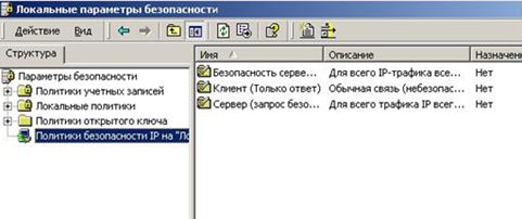
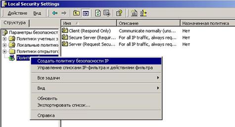
Figure 5.2.13-5.2.14 – Creation of a new security policy
Figure 5.2.15 -Wizard IP Policy
In the resulting dialog box, enter the policy name and description (Fig. 5.2.16)
Figure 5.2.16 – Dialog box for policy name and description
In the next window, mark the «Use the default rule» (Fig. 5.2.17)
Figure 5.2.17 – Agree with default rule
|
|
|
In this window, leave all the default settings (Fig. 5.2.18).
Figure 5.2.18 – Some default settings
In the next window remove the check mark - property policy will be edited later (Fig. 5.2.19).
Figure 5.2.19 – Removing of the check mark for later edition
Now politic has appeared in the list created by the policy (Fig. 5.2.20).
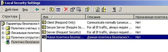
Figure 5.2.20 – Appearance of the created policy
5.2.7.2 Create a new filter action. By right-clicking on the «Security Policy IP", select «Manage Lists IP-filter and filter actions» (Fig. 5.2.21).
Figure 5.2.21 – Management of Lists IP-filter and filter actions
In the window that appears, go to the tab «Manage filter actions» (Fig. 5.2.22).
Figure 5.2.22 – Management of filters action
Click «Add» button - to add the action «filter ban» (Fig. 5.2.23).
Figure 5.2.23 – Wizard for filter action to add
In the window that give the name of the action of the filter and its description (Fig. 5.2.24).
Figure 5.2.24 – Entering the name and description for action
In the window that appears, select the action - «Block» (Fig. 5.2.25).
Figure 5.2.25 – Selection of the filter action
Thus was created the first rule - banned all types of services, and will continue to allow those services (open ports) are required.
In last window press the “Done”, select «Edit Properties» to be installed (Fig. 5.2.26).
Figure 5.2.26 – Finishing of the installation
In the window there was a new line of action (Fig. 5.2.27).
Figure 5.2.27 – Action of filter obtained
5.2.7.3 Editing the established security policy. Click twice left click on the name of security policy. In the window «Properties» to change the properties of established policies push the button «Add» (Fig. 5.2.28).
Figure 5.2.28 – Changing the policy properties
See a wizard for creation new rules of security policy in Figure 5.2.29.
Figure 5.2.29 – Wizard for creation of the new rules of policy
In the next window, leave everything unchanged (Fig. 5.2.30).
Figure 5.2.30 – Don’t assign a tunnel
In the next window, specify, for which the connection will operate this rule. In the case of an excited this rule will apply to all network connections (Fig. 5.2.31).
Figure 5.2.31 – Rule applies all network connections
In this window, leave everything unchanged (Fig. 5.2.32).
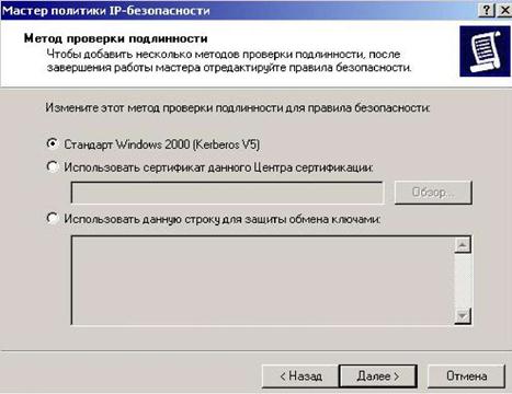
Figure 5.2.32 – Window without changes
In this window it is necessary to choose the filter which forbids all types of services for all. As the necessary filter in the list isn't present, he is necessary for adding. For this purpose we press the “Add” button (Fig. 5.2.33).
Figure 5.2.33 – Adding of the new filter
In the opened window we entitle the filter and it is described its actions. Further we press the “Add” button (Fig. 5.2.34)
Figure 5.2.34 – Name and description of the new filter
The master of creation of the filter is started (Figure 5.2.35).
Figure 5.2.35 – Starting wizard for the new filter
 In a window we specify a source of packages (the address of senders) since the filter should not pass packages from all, we specify any IP address (Fig. 5.2.36).
Figure 5.2.36 -Specifying a source of packages
|
|
|
In the following window the address of the recipient of a package as the filter should forbid packages from all sources to ours of a host, we specify «my IP address» (Fig. 5.2.37).

Figure 5.2.37 -Specifying a recipient of packages
In the following window without establishing a tag «To change properties» we press «ready» (Fig. 5.2.38).
Figure 5.2.38 – Wizard finishing
The new filter is created (Fig. 5.2.39).
Figure 2.39 – Filter created
In a window of existing filters we choose the created filter and we press «Next» (Fig. 5.2.40):
Figure 5.2.40 – Choosing of created filter
In the opened window we choose action for the filter, in this case we choose created by us in point 5.2.7.2 action – «The ban filter» and we press «Next» (Fig. 5.2.41).
Figure 5.2.42 – Choosing action for the fulter
In this window without establishing a tag «To change properties» we press «ready» (Fig. 5.2.43).
Figure 5.2.43 – Wizard finished
A new rule appeared in the created policy (Fig. 5.2.44).
Figure 5.2.44 – Appearance of the filter added
5.2.7.4 Application of the created policy. For application of policy we select it. We press the right button and choose “Apply” (Fig. 5.2.45).
Figure 5.2.45 – Applying of the policy created
5.2.7.5 Permission of services (opening of ports). After prohibition of all services as required it is possible to open some main services. For permission of services we cancel the created policy and edit it. First of all it is necessary to permit ISMP traffic (for work of the utility ping). For editing of policy open its properties and on a tab of «Rule» press “add”, the master of creation of new rules is started. The following 4 steps are similar described in point 5.2.7.3.
Having reached a window «List of filters», we will use already existing filter permitting ICMP traffic for permission of the ICMP protocol (Fig. 2.46).
Figure 2.46 -Filter permitting ICMP traffic
In the following window it is necessary to specify operation of the filter since we permit ICMP traffic, that we choose action “Permit” (Fig. 5.2.47).
Figure 5.2.47 – Action for ICMP filter (permission)
Having pressed the Next button the new filter is created. Now in the created policy appeared one more new rule permitting ICMP protocol work.
Figure 5.2.48 – One more new rule in created policy
|
|
|
|
|
Дата добавления: 2014-12-27; Просмотров: 564; Нарушение авторских прав?; Мы поможем в написании вашей работы!