КАТЕГОРИИ:
Архитектура-(3434)Астрономия-(809)Биология-(7483)Биотехнологии-(1457)Военное дело-(14632)Высокие технологии-(1363)География-(913)Геология-(1438)Государство-(451)Демография-(1065)Дом-(47672)Журналистика и СМИ-(912)Изобретательство-(14524)Иностранные языки-(4268)Информатика-(17799)Искусство-(1338)История-(13644)Компьютеры-(11121)Косметика-(55)Кулинария-(373)Культура-(8427)Лингвистика-(374)Литература-(1642)Маркетинг-(23702)Математика-(16968)Машиностроение-(1700)Медицина-(12668)Менеджмент-(24684)Механика-(15423)Науковедение-(506)Образование-(11852)Охрана труда-(3308)Педагогика-(5571)Полиграфия-(1312)Политика-(7869)Право-(5454)Приборостроение-(1369)Программирование-(2801)Производство-(97182)Промышленность-(8706)Психология-(18388)Религия-(3217)Связь-(10668)Сельское хозяйство-(299)Социология-(6455)Спорт-(42831)Строительство-(4793)Торговля-(5050)Транспорт-(2929)Туризм-(1568)Физика-(3942)Философия-(17015)Финансы-(26596)Химия-(22929)Экология-(12095)Экономика-(9961)Электроника-(8441)Электротехника-(4623)Энергетика-(12629)Юриспруденция-(1492)Ядерная техника-(1748)
Making Assembly Drawing
|
|
|
|
Assembly Drawings
QuestionS for SELFcheck
1. What is detail drawing of a part?
2. What is asketch?
3. What is the basic requirements to the detail drawings and sketches?
4. What steps should be followed to make sketches?
5. Denotation roughness of surfaces of the parts.
Assembly drawing shows how the components or parts must be assembled to form the complete machine or device. The assembly drawing shows the different parts in their relative positions. An assembly drawing furnishes the following information:
a) One main view to show the best assembly.
b) Selected overall dimensions and important centre to centre distance.
c) Identification of different parts on assembly drawing.
d) Necessary sectional views.
e) Part list, notes, titles, etc.
An assembly drawing is a document, which contains the representation of assembly unit and other information, necessary for its assembly and control. An assembly drawing must give the complete information about an article construction, interaction of parts, that belong to it, and there is a technical document during implementation of assembly operation and acceptance of an article.
An assembly drawing must contain:
А) representation of an assembly unit, which gives an idea of placing and interconnection of its separate parts;
B) sizes and other parameters and requirements, which are carried out and controlled in the process of an assembly of an article, pointing about the method of connection of parts of an article;
C) part number of component parts of an article;
D) basic descriptions of an article;
E) overall, setting dimension, conjunctive and reference dimensions (fig.7.1).
1. Necessary and sufficient amount of representations are determined thus, the external and internal elements of an article were fully exposed on an assembly drawing.
2. The scale of a drawing is determined depending on complication of an article and its sizes, a paper format is chosen according to State Standard 2.301-68. A frame and title block are drawn.
3. Overall rectangles or circles are marked for placing of representations and the axes of symmetry are drawn.
4. Necessary sectional views, sections, additional representations are drawn. If any sectional view is to be drawn, fix the position of the cutting plane and find out the parts through which cutting plane passes. Difficult parts are drawn simultaneously on all of representations of an article.
5. Other parts are drawn.
6. The executed drawing is checked up, the lines of visible and invisible contours are drawn, sectional views and sections are shaded. Change hatching directions in adjacent sectioned components.
7. Extension and dimension lines are drawn and size numbers are marked.
8. Part numbers of component parts of an assembly unit are marked.
9. A title block is filled in, technical requirements and technical description of an article is shown in case of necessity.
If an article is designed in a shape of a symmetric figure, it is recommended to combine the half of view with the half of the proper sectional view. Fixing, keys, connecting rods, axles and shafts in a longitudinal section are drawn undissected. Such elements, as spokes of fly-wheels, pulleys, gear-wheels, thin walls as stiffening ribs are cut, but are drawn unshaded, if a cutting plane passes along an ax or a long side of such element.
Shadings of one part in sectional views on different representations are drawn under one angle, maintaining the identical interval of shading. Shadings of contiguous parts are drawn in different directions.
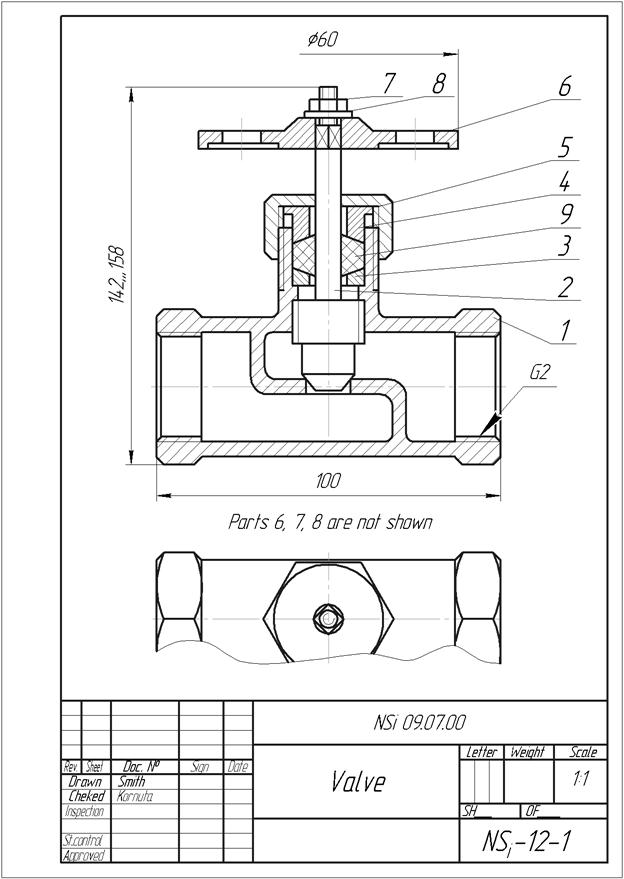
Figure7.1 – Assembly drawing
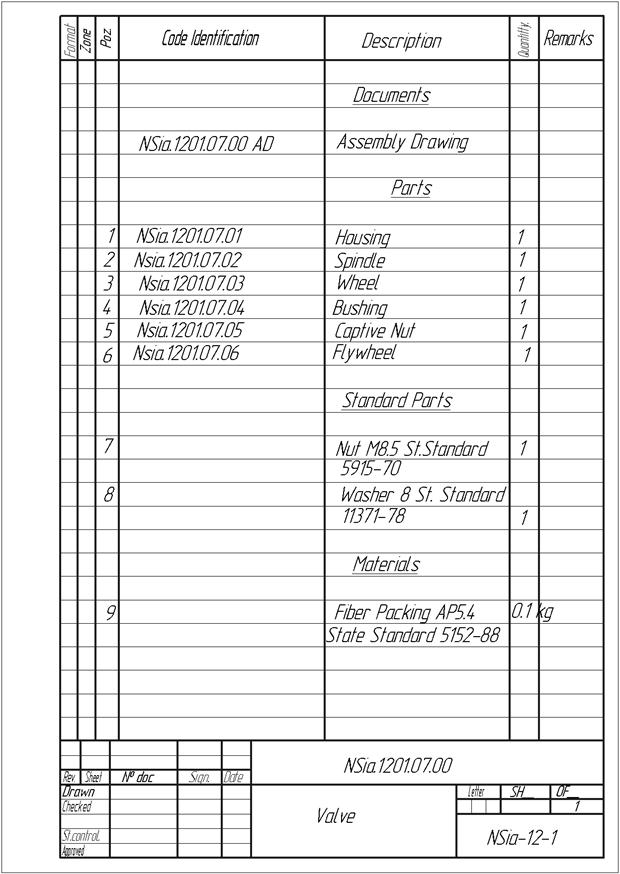
Figure 7.2 – A parts list
An assembly drawings are done, as a rule, with simplifications and conventions.
|
|
|
|
|
Дата добавления: 2014-10-15; Просмотров: 493; Нарушение авторских прав?; Мы поможем в написании вашей работы!