КАТЕГОРИИ:
Архитектура-(3434)Астрономия-(809)Биология-(7483)Биотехнологии-(1457)Военное дело-(14632)Высокие технологии-(1363)География-(913)Геология-(1438)Государство-(451)Демография-(1065)Дом-(47672)Журналистика и СМИ-(912)Изобретательство-(14524)Иностранные языки-(4268)Информатика-(17799)Искусство-(1338)История-(13644)Компьютеры-(11121)Косметика-(55)Кулинария-(373)Культура-(8427)Лингвистика-(374)Литература-(1642)Маркетинг-(23702)Математика-(16968)Машиностроение-(1700)Медицина-(12668)Менеджмент-(24684)Механика-(15423)Науковедение-(506)Образование-(11852)Охрана труда-(3308)Педагогика-(5571)Полиграфия-(1312)Политика-(7869)Право-(5454)Приборостроение-(1369)Программирование-(2801)Производство-(97182)Промышленность-(8706)Психология-(18388)Религия-(3217)Связь-(10668)Сельское хозяйство-(299)Социология-(6455)Спорт-(42831)Строительство-(4793)Торговля-(5050)Транспорт-(2929)Туризм-(1568)Физика-(3942)Философия-(17015)Финансы-(26596)Химия-(22929)Экология-(12095)Экономика-(9961)Электроника-(8441)Электротехника-(4623)Энергетика-(12629)Юриспруденция-(1492)Ядерная техника-(1748)
Starting of DC motor with independent excitation to the main speed at multistage of starting rheostat
|
|
|
|
Start transition of DC motor with independent excitation to the main speed at multistage of starting rheostat is realized by the next scheme (at thrice-stage of starting rheostat):
Analysis of electromagnetic constant(equation 5.5)

Shows, that if speeding-up occurs, the resistance of armature circuit should be reduced, but this action leads to the current increasing at start. Mentioned starting way of DC motor with independent excitation with constant (at start-time) resistance allows decreasing starting current to desirable, starting time is pretty substantial. Multistage starting (with gradual bringing in stages of starting rheostat) allows staying starting current. Starting time decreases in this way, because constant decreases as well at bringing out stages of rheostat resistors.
Some limits of starting deviation of current and, therefore moment, are specified at starting DC motor with independent excitation – I1 and I2
I1=Imin=(1.1-1.2)Irat – minimal switching current.
This current should be greater than rated one by 10-20% to make the starting exact at the gratest (rated) load.
I2=Imax=(2.2-2.6)Irat – maximal switching current (it is used at the very starting.)
This current is right to increase, in order to reduce transition regime time, so to improve acceleration action. But it can`t be greater than rated one more than in 2.5 times, because heating increases and switching gets worse.
SO the starting diagram of DC motor with independent excitation looks the following: (at thrice-stage rheostat)
At the figure R1;R2;R3 and R are signed in the scale, that is increased in I2/Iс times
As the starting rheostat is bringing in the armature circuit resistance decreases (T decreases), so it leads to decreasing time of armature starting (time constant decreases)
R1>R2>R3, as t1>2t>t3

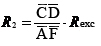
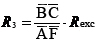
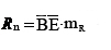
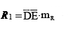
Value of resistances of starting rheostat stages Rn(Rn=R1+R2+R3) can be found graphically. '
R'1 = Rn+Rexc=R1+R2+R3+Rexc;
R'2 = R2+R 3+Rext;
R'3 = R3+Rext;
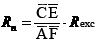 ;
;
 - rated motor resistance
 ;
; ;
; ,
,
or:
 ;
; ;
; ;
; ,
,
where  - resistance scale
Diagram of DC motor with IE starting looks following:
. 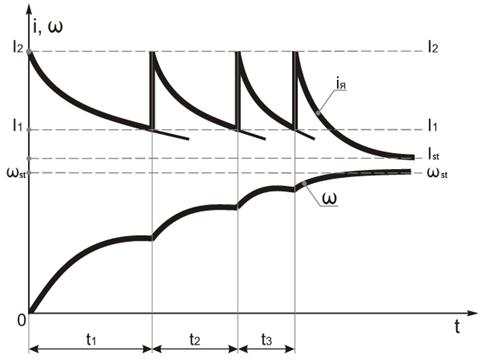
It is distinctive, because motor current is deviating at starting in the I1 and I2 limits, at the very start Ist=I2, then as armature is speeding up, motor EMF increases as well, thus its current starts decreasing, as the moment does. When current is up to I1 magnitude the first stage R1 of Rstresistior should be switched off, so armature current to be up to I2, and so on. Analogically angular speed curve is depicted.
5.5 Starting of DC motor with independent excitation taking into account electromagnetic transient process
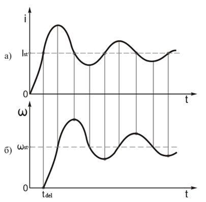
When time of electromagnetic transient processes is commensurable to time of electromechanical processes, Influence of electromagnetic induction should be taken into account. Starting characteristics look the following (Um=const)
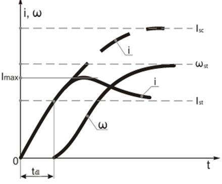
It is obvious that process of starting consists of two stages.
1st stage. The motor is motionless till the current is up to magnitude that is necessary to create motion moment. At this stage increasing of armature current depends on the speed of magnetic process flowing that is defined by equation of armature circuit voltage.
 (5.9)
(5.9)
Solution of this equation ( )is a result of rule of armature current changing as armature is immovable.
 , (5.10)
where:  - short-circuit current of motor, [ А ];
 - electromagnetic time constant of armature circuit, [ с ].
Armature current curve is in limits from 0 up to  , which is defined by 5.10 equation
– time of delay. It is defined in 5.10 by substitution in 5.10
 .
.
Then 5.10 looks:
 (5.11)
2nd stage.Armature starts to rotate after delay time. Angular velocity increases, EMF of armature appears, it affects the armature current. Then both processes (electromagnetic and electromechanical) progress simultaneous, they are integrated transient process of starting DC motor with IE.
Calculation of armature current and angular velocity of motor (Ф=const) should be done on basis of equilibrium equation of armature circuit voltage and motion equation
 ,
,
or
 ,
,  (5.12)
 (5.13)
Have divided 5.13 by k, as k isn`t equal to 0, we have:
 ,
,
 . (5.14)
Common solution of 5.12 and 5.14 is two linear differential equatons of the 2nd order (relatively of current iar, and angular velocity w).
Integration of those equations result two dependence
 ,
,
 ,
,
Which are depicted on the previous diagram in the time interval  .
.
At the interval  there is a current, which is changing at the motionless armature only (1st stage). Change of armature current designed with dashed line, if there was just transient process (1 stage) to the equation 5.10
It is obvious, speed has asymptotic nature tends to the  magnitude, and current crosses asymptote
  and has its maximum
  and then tends to
  . Magnitude of depends on relation of
  and
and .
.
Real ratio andcan have such value, that Imax to exceed permissible current taking into account conditions of magnitude commutation quality at the direct start (( – low, because Ra= Rae+ Ram, and Ra=0),). That is why direct start is possible for DC motors with independent excitation with power up to (0,5÷1,0) kwt. If greater power takes place starting should be done using additional resistor in the armature circuit. is getting less, аndis getting greater and
  . Starting current peak could be get less if the coil switch in the armature circuit, but the oscillations can take place. Damped oscillations increase starting time, the substantial velocity overshoot occurs and efficiency of peak current limiting decreases.
With the coil in the armature circuit current(a) and start velocity(b) curves look:
Coil presence in the armature circuit increase the dependence between w and M (the dependence is stated be static mechanical characteristic). Cause inductance in the armature circuit distorts static characterictics of DC motors with IE at transient modes.
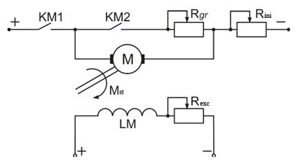
5.6 Transient mode of dynamic braking of DC motor with independent excitation
Let us remind essence of braking. If in the operated motor (in the motor mode) linear contactor switch KM1 switches off armature circuit and contactor KM2 connects it with dynamic braking resistor Rde, then motor is in the generator mode of dynamic braking, if exciting winding LM is supplied by DC current still.
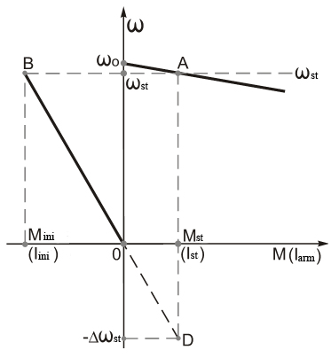
Motor mode with a load Me at point A. As KM1 is switched off and KM2 is switched on motor is in dynamic braking mode(generator mode) to the point Bwith initial braking moment Minit, and then starts to break rapidly at distance BC to the moment of stop in the point C (or 0 moment). If there is need to put the load down instead of breaking, then after reverse moment system accelerates in the point D, load will go down with the constant speed -dwc
Voltage Equilibrium equation and motion equation for the case of dynamic braking look:
 (5.15)
 , (5.16)
where  - armature EMF;
 (right part of eq-n 5.15), motor is off;
 - armature circuit resistance;
 - motor moment;
 - dynamic moment.
Common solution (5.15) and (5.16) gives a result:
 , (5.17)
де  – integration constant is determined by initial conditions (
 ).
).
1st condition:  accordingtotheupperpartof
 (figure 5.10), thus
 - initial velocity at the moment of switching the motor from motor mode to the dynamic braking one.
2nd condition:  accordingtothelowerpartof
 , thus
 - ultimate value of velocity difference, which is determined from the dynamic breaking characteristic at the resistor moment
 (point).
After substitution B we obtain in the equation 5.17:
 (5.18)
At dynamic braking without load Mc=0:

And equation 5.18 can be rewritten:
 . (5.19)
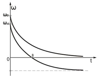
Dynamic characteristics w=f(t),which are built by the equation 5.18(under load), look the following:
At the braking under the load (1 characteristic) curve tends asymptotically to the angular velocity –dwc (at the active static moment), and if the moment of static resistance is reactive moment, then braking stoppes at angular velocity w=0 (point B)
At the braking without load (2nd characteristic) curve asymptotically tends to 0 , and initial velocity is:
 .
.
5.7 Transient modes in ED with traditional asynchronous motors
At 1st approximation they can be considered with neglecting of electromagnetic processes, as they are flowing faster than electromechanical processes.
Starting of squirrel-cage AC motor of low and middle power is done with full supply voltage (direct starting). To limit the moment or current starting of squirrel-cage motor is realized with resistors or reactance, switched in the stator circuit (with lower voltage or thyristor valves of voltage)
Starting of induction motor is realized with starting resistor switched in the rotor circuit.
To make things simple let`s consider AC motor is started at the idle mode (Mc=0) in one stage resistor.
Motor moment is defined by simplified Kloss`sformula(for , satisfies
 ):
):
 , (5.20)
where  ;
;
 ; (5.21)

Then 5.20 is:
 . (5.22)
As definition of sliding is: velocity is:
 . (5.23)
Derivative of 5.23 is
 (5.24)
\Value of derivative 5.24 substitute in 5.22 and we`ll obtain:
 . (5.25)
In equation 5.25 variable are separated, then:
 , (5.26)
as - electromechanical time constant, then equation 5.26 is:
 (5.27)
Integrating equation (5.27) we`ll obtain the starting time of asynchronous motor without a load:
 .
.
At the starting at idle mode ( ) starting time is defined from the equation 5.27. Time is defined the following way:
 .
.
From the other hand it is possible to consider, that rotor of asynchronous motor approaches w0a the infinitely large starting time.
if , then
 .
.
But in the real conditions starting can be considered to be complete, when current value of sliding differs not more than 0.05 of its steady value, then starting time without a load is:
 . (5.28)
In the numerator of the first ratio the magnitude of 0.05 2 can neglected, the 5.28 looks:
 .
.
Останній If the last expression is divided by Tm (i.e. time to transfer into relative units), then:
 . (5.29)
Relative starting time depends on the critical value of scr, as it cam be seen in the 5.29. Using 5.29 it can be stated that  has its the least value at
 .
.
Thus, minimal starting time is relative time
 at .
at .
6. ELECTRIC MOTOR CHOICE
Electric drive Design process starts from the substantiation of demands to it and devise in concordance with listed demands, Electrical drive in the current type and principle of operating.
Basic variants are depicted in the figure, which are obtained a supply from AC and DC sources.
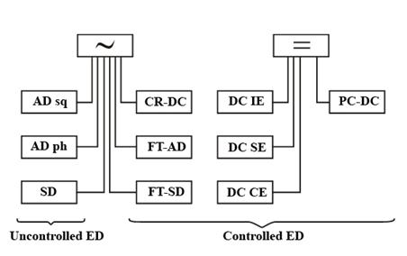
Hint: CR – controlled rectifier, FT- frequency transfer, PC- pulse converter.
Searching for Matching variants should be started from the simplest things. If it is uncontrolled ED, then AM with squirrel-cage, if current surges take place the inductive motor, if continuous operation with switching off – synchronous motor.
If ED is controlled then it should be started from the basic indicators of velocity control (range, moment changing character, allowable moment and so on).
Reliable and economical ED operation is possible at the right choice of type and power of electric drive.
Power of motor should be chosen with the strict conformity with operation mode and expecting load.
Extra-power is not reasonable because of increasing of overall ED dimensions, its mass and initial prize. Energetic characteristics of unload machine are getting worse (efficiency, cosφ)
At the operation of appropriate electrical motor, short-term load surges can take place, which are greater than motor capacity. They do not heat EM noticeable, but in this case if overload approaches some limit, normal operating load is destroyed.
So the following facts should be taken into account in the choise of EM:
-value of instantaneous overload;
-heating.
Choosing of Electric drive in case of overload means to specify nominal moment from the value of overload motor ability.

l - overload motor ability.
It is used overload ability by current

 .
.
Overload ability of DC motor depends on commutation substantively (i.e. overload is limited by allowable sparking in the commutator in case of overload)
 ,
,
де  - EMF of commutating part;
 - reactive EMF
 - Commutation EMF is created by flux of additional poles;
 - EMF of transformer, which is induced by magnetic flux of basic pole pair.
Magnitude l of DC motor shouldn’t be less than 2.5 in the long operating term.
 .
.
Overload ability of asynchronous motor is limited with magnitude of moment at the maximal sliding. It is less than DC motor one.
 .
.
From the other hand, asynchronous motor moment depends on  , and standard states the moment decay to the 90% of rated one, that is why λ should be calculated as 0.7-0.8 of rated one.
Overload ability of synchronous motor is the greatest. It is 3-3.5.
Rated power of EM is limited by heating, i.e. by heat resistance of using materials. In other words it depends on class of insulation (Y A E B F H C). So A class has temperature 105°С and C class has 180°С
Experience says even tiny insulation overheating reduces service life of EM. The other factors should be mentioned besides overload and overheating.
Ways of airing and types of protection from acting of environment.
Appropriate chose of motor with these factors determines motor life, reliability and its servicing safety.
By type of airing motors are divided into natural airing motors and forced airing. If chosen motor has self-airing, and its speed can be regulated from rated to the lower one, then the issue of airing is stated for the low velocity.
By the environment motor protection Motors are divided:
-open version;
-protecting version;
-Closed version;
-sealed version.
Protecting version is subdivided:
-drip-proof (protects motor from the drip hitting inside, which hit on the cover of motor vertically or 60 degrees on-the-mitre);
-splash-proof (protects motor from hitting the drip and splashes inside, that are hitting from any direction)
Sealed motors operate submerged. This type of motors is of submerged type – motor operates submerged under hydrostatic pressure.
Embodiment as provided by integration with operating device:
-one or two shaft out;
-form of shaft out(cylindrical, conic etc);
-way of shaft connection (shaft, spline);
-way of mounting (supporting motor, flange-mounted motor so on.)
At the motor chose not only steady modes should be taken into account but transient ones as well. (starting, reverse, speed regulating, braking) To make it clear the load charts are used.
 .
.
It should be mentioned that every chosen motor should be loaded completely, but not be overheating. It should provide normal operation at any short-time overloads and starting characteristics.
|
|
|
|
|
Дата добавления: 2014-01-05; Просмотров: 1247; Нарушение авторских прав?; Мы поможем в написании вашей работы!