КАТЕГОРИИ:
Архитектура-(3434)Астрономия-(809)Биология-(7483)Биотехнологии-(1457)Военное дело-(14632)Высокие технологии-(1363)География-(913)Геология-(1438)Государство-(451)Демография-(1065)Дом-(47672)Журналистика и СМИ-(912)Изобретательство-(14524)Иностранные языки-(4268)Информатика-(17799)Искусство-(1338)История-(13644)Компьютеры-(11121)Косметика-(55)Кулинария-(373)Культура-(8427)Лингвистика-(374)Литература-(1642)Маркетинг-(23702)Математика-(16968)Машиностроение-(1700)Медицина-(12668)Менеджмент-(24684)Механика-(15423)Науковедение-(506)Образование-(11852)Охрана труда-(3308)Педагогика-(5571)Полиграфия-(1312)Политика-(7869)Право-(5454)Приборостроение-(1369)Программирование-(2801)Производство-(97182)Промышленность-(8706)Психология-(18388)Религия-(3217)Связь-(10668)Сельское хозяйство-(299)Социология-(6455)Спорт-(42831)Строительство-(4793)Торговля-(5050)Транспорт-(2929)Туризм-(1568)Физика-(3942)Философия-(17015)Финансы-(26596)Химия-(22929)Экология-(12095)Экономика-(9961)Электроника-(8441)Электротехника-(4623)Энергетика-(12629)Юриспруденция-(1492)Ядерная техника-(1748)
Conventional drawing of fixings and joints
|
|
|
|
SCREW JOINT
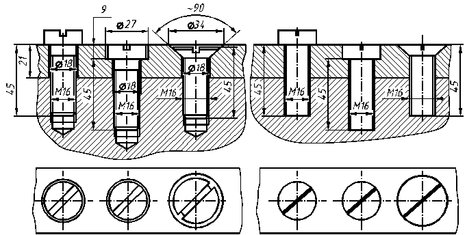
The thickness of an overhead joining part and parameters of a screw are input data for the drawing of a screw joint. At the structural drawing of a screw joint (fig. 4.24, а, b, c) it is necessary to draw all structural elements of parts. The sizes of a thread, length of a screw and sizes of a base surface under a head fill in. A slot under a screwdriver is disposed under the corner 45° at the view from the face head. On the simplified drawing of a screw joint (fig. 4.24, d, e, f) the sizes of a thread and a length of a screw are marked. A slot under a screwdriver is represented an incrassate contour line. The thread opening under a screw is drawn like an opening under a stud.

а) b) c) d) e) f)
Figure 4.24 – The screw joint
The parameters of a base surface under a head of screw are regulated by State Standard 12876:2008.
The conventional drawing of fixings (table 4.11) is regulated by State Standard 2.315:2008. Fixings for which on a drawing the diameter of a bar is equal 2 mm or less is shown conventionally. Conventional drawing and its sizes must give exhaustive and necessary information about the view of a joint and its components.
Table 4.11 - The conventional drawing of fixings
| Name of a part | View | Drawing | Name of a part | View | Drawing |
| Round-head and cheese-head bolts and screws | Main (front) | 
| Nuts | Main (front) | 
|
| Top | 
| Top | 
| ||
| Bottom | · | Washers | Main (front) | 
| |
| Countersunk-head and oval-head screws | Main (front) | 
| Top | ||
| Top | 
| Studs | Main (front) | 
| |
| Bottom | · | Top | · |
In fig.4.25 the examples of conventional drawings of thread joints are resulted: a – by a bolt on a view and in a section; b – by a stud on a view and in a section; c – by a countersunk-head screw on a view and in a section; d –by a cheese-head screw on a view and in a section.

а) b) c) d)
Figure 4.25 – Conventional drawings of thread joints
|
|
|
|
|
Дата добавления: 2014-10-15; Просмотров: 311; Нарушение авторских прав?; Мы поможем в написании вашей работы!