КАТЕГОРИИ:
Архитектура-(3434)Астрономия-(809)Биология-(7483)Биотехнологии-(1457)Военное дело-(14632)Высокие технологии-(1363)География-(913)Геология-(1438)Государство-(451)Демография-(1065)Дом-(47672)Журналистика и СМИ-(912)Изобретательство-(14524)Иностранные языки-(4268)Информатика-(17799)Искусство-(1338)История-(13644)Компьютеры-(11121)Косметика-(55)Кулинария-(373)Культура-(8427)Лингвистика-(374)Литература-(1642)Маркетинг-(23702)Математика-(16968)Машиностроение-(1700)Медицина-(12668)Менеджмент-(24684)Механика-(15423)Науковедение-(506)Образование-(11852)Охрана труда-(3308)Педагогика-(5571)Полиграфия-(1312)Политика-(7869)Право-(5454)Приборостроение-(1369)Программирование-(2801)Производство-(97182)Промышленность-(8706)Психология-(18388)Религия-(3217)Связь-(10668)Сельское хозяйство-(299)Социология-(6455)Спорт-(42831)Строительство-(4793)Торговля-(5050)Транспорт-(2929)Туризм-(1568)Физика-(3942)Философия-(17015)Финансы-(26596)Химия-(22929)Экология-(12095)Экономика-(9961)Электроника-(8441)Электротехника-(4623)Энергетика-(12629)Юриспруденция-(1492)Ядерная техника-(1748)
Charging System. Regulator Circuit Check
|
|
|
|
ELECTRICAL SYSTEM 16-31
Regulator Circuit Check
NOTE
Rectifier Circuit Inspection
Charging System
ELECTRICAL SYSTEM
Rectifier circuit check
• Remove the left side cover (see Side Cover Removal in
the Frame chapter).
Disconnect the regulator/rectifier lead connector [A].
Brown Lead Terminal [A] White/Red Lead Terminal [B] Black Lead Terminal [C] Yellow 1 Lead Terminal [D] Yellow 2 Lead Terminal [E] Yellow 3 Lead Terminal [F]
• Connect the hand tester to the regulator/rectifier as shown in the table, and measure the resistance of the respective diodes in both directions, in the sequence in the table.
•The measured resistance should be small in one direction and 10 or more times in the other direction. If the measured resistance of any of the two wires (White/Red or Yellow) is small or large in both directions, the rectifier is damaged; therefore, replace the regulator/rectifier.
| 1 2 3 4 5 6 7 8 9 10 11 12 | Connecting terminal | Standard | Tester range |
| Tester positive (+) terminal | Tester negative (–) terminal | ||
| Y1 | W/R | OO | × 10 0 or × 100 0 |
| Y2 | |||
| Y3 | |||
| Y1 | BK | Approximately 1/2 of the entire graduation | |
| Y2 | |||
| Y3 | |||
| W/R | Y1 | ||
| Y2 | |||
| Y3 | |||
| BK | Y1 | OO | |
| Y2 | |||
| Y3 |
○The actual resistance measurement varies with the tester used and the individual diodes, Generally speaking, it is acceptable if the tester’s indicator swings approximately halfway.
• Prepare the following:
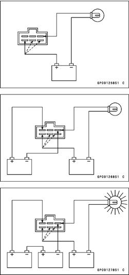
Test Light Bulb: one 12 V 3.4 W bulb Batteries: three 12 V batteries Wires: six wires of appropriate lengths
CAUTION
The test light works as an indicator and also a current limiter to protect the regulator/rectifier from excessive current. Do not use an ammeter instead of a test light.
• Check to be sure the rectifier circuit is normal before con
tinuing.


|
Regulator Circuit Test-1st Step:
• Connect the test light and the 12V battery to the regulator/rectifier as shown.
• Check Y1, Y2, and Y3 terminal respectively.
• If the test light turns on, the regulator/rectifier is defective. Replace it.
• If the test light does not turn on, continue the test.
Regulator Circuit Test-2nd Step:
• Connect the test light and the 12V battery in the same manner as specified in the "Regulator Circuit Test-1st Step".
• Apply 12 V to the BR (voltage monitoring) terminal.
• Check Y1, Y2, and Y3 terminal respectively.
• If the test light turns on, the regulator/rectifier is defective. Replace it.
• If the test light does not turn on, continue the test.
Regulator Circuit Test-3rd Step:
• Connect the test light and the 12 V battery in the same manner as specified in the "Regulator Circuit Test-1st Step".
• Momentarily apply 24 V to the BR terminal by adding a 12 V battery.
Check Y1, Y2, and Y3 terminals respectively.
|
|
|
|
|
Дата добавления: 2014-12-23; Просмотров: 427; Нарушение авторских прав?; Мы поможем в написании вашей работы!