КАТЕГОРИИ:
Архитектура-(3434)Астрономия-(809)Биология-(7483)Биотехнологии-(1457)Военное дело-(14632)Высокие технологии-(1363)География-(913)Геология-(1438)Государство-(451)Демография-(1065)Дом-(47672)Журналистика и СМИ-(912)Изобретательство-(14524)Иностранные языки-(4268)Информатика-(17799)Искусство-(1338)История-(13644)Компьютеры-(11121)Косметика-(55)Кулинария-(373)Культура-(8427)Лингвистика-(374)Литература-(1642)Маркетинг-(23702)Математика-(16968)Машиностроение-(1700)Медицина-(12668)Менеджмент-(24684)Механика-(15423)Науковедение-(506)Образование-(11852)Охрана труда-(3308)Педагогика-(5571)Полиграфия-(1312)Политика-(7869)Право-(5454)Приборостроение-(1369)Программирование-(2801)Производство-(97182)Промышленность-(8706)Психология-(18388)Религия-(3217)Связь-(10668)Сельское хозяйство-(299)Социология-(6455)Спорт-(42831)Строительство-(4793)Торговля-(5050)Транспорт-(2929)Туризм-(1568)Физика-(3942)Философия-(17015)Финансы-(26596)Химия-(22929)Экология-(12095)Экономика-(9961)Электроника-(8441)Электротехника-(4623)Энергетика-(12629)Юриспруденция-(1492)Ядерная техника-(1748)
Removal
|
|
|
|
40 Remove the distributor (see Chapter 5B). Remove the timing belt and camshaft sprocket (see Sections 5 and 9).
41 Measure the camshaft thrust clearance (endfloat) with a dial indicator (see illustration). If the clearance is greater thanthe service limit, renew the camshaft and/or the cylinder head.
42 Position the knock pin in the exhaust camshaft just above the top of the cylinder head (see illustration). This will position the intake camshaft lobes so the camshaft will be pushed up evenly by valve spring pressure.
Caution: This positioning is important to avoid damaging the cylinder head or camshaft as the camshaft is removed.

| 10.41 With the dial zeroed, lever the | 10.42 Place the exhaust camshaft knock | 10.43 Remove the two bolts and the right- |
| camshaft forward and back, then read the | pin between the 9 o'clock and 10 o'clock | hand camshaft bearing cap from the intake |
| endfloat on the dial | positions | camshaft |
Engine in-car repair procedures 2A•15
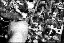
43 Remove the two bolts and the right-hand bearing cap from the intake camshaft (see illustration).
44 Secure the intake camshaft sub-gear to the main gear by installing one of the service bolts into the threaded hole (see illustration).
45 Following the reverse of the tightening sequence (see illustration 10.70), loosen the remaining intake camshaft bearing cap bolts in 1/4-turn increments until the bolts can be removed by hand. Lift the bearing caps straight up and off.
Caution: As the centre bearing cap bolts are being loosened, make sure the camshaft is moving up evenly. If one end or the other stops moving and the camshaft gets jammed, start over by refitting the bearing caps. DO NOT try to lever or force the camshaft out.
46 Lift the camshaft straight up and out of the cylinder head.
47 Position the knock pin in the exhaust camshaft at approximately the 5 o'clock position (see illustration).
48 Remove the right-hand exhaust camshaft bearing cap bolts and detach the bearing cap and oil seal.
Caution: Do not lever the cap off. If it doesn't come loose easily, leave it in place without bolts.
49 Following the reverse of the tightening sequence (see illustration 10.60), loosen the remaining exhaust camshaft bearing cap bolts in 1/4-turn increments until the bolts can be removed by hand. Lift off the bearing caps.
Caution: As the centre bearing cap bolts are being loosened, make sure the camshaft is moving up evenly. If one end or the other stops moving and the camshaft gets jammed, start over by refitting the bearing caps and resetting the knock pin. DO NOT try to lever or force the camshaft out.
50 Lift the camshaft straight up and out of the cylinder head.
51 Clean the oil off the camshaft follower shims, mark them with a felt-tip marker and remove the followers, keeping the shims with their followers (see illustration 10.11a).
Store the camshaft bearing caps, followers and shims so they can be reinstalled without mixing them up (see illustration 10.11b).
52 Position the intake camshaft in a vice,

|
|
|
|
|
Дата добавления: 2014-12-23; Просмотров: 495; Нарушение авторских прав?; Мы поможем в написании вашей работы!