КАТЕГОРИИ:
Архитектура-(3434)Астрономия-(809)Биология-(7483)Биотехнологии-(1457)Военное дело-(14632)Высокие технологии-(1363)География-(913)Геология-(1438)Государство-(451)Демография-(1065)Дом-(47672)Журналистика и СМИ-(912)Изобретательство-(14524)Иностранные языки-(4268)Информатика-(17799)Искусство-(1338)История-(13644)Компьютеры-(11121)Косметика-(55)Кулинария-(373)Культура-(8427)Лингвистика-(374)Литература-(1642)Маркетинг-(23702)Математика-(16968)Машиностроение-(1700)Медицина-(12668)Менеджмент-(24684)Механика-(15423)Науковедение-(506)Образование-(11852)Охрана труда-(3308)Педагогика-(5571)Полиграфия-(1312)Политика-(7869)Право-(5454)Приборостроение-(1369)Программирование-(2801)Производство-(97182)Промышленность-(8706)Психология-(18388)Религия-(3217)Связь-(10668)Сельское хозяйство-(299)Социология-(6455)Спорт-(42831)Строительство-(4793)Торговля-(5050)Транспорт-(2929)Туризм-(1568)Физика-(3942)Философия-(17015)Финансы-(26596)Химия-(22929)Экология-(12095)Экономика-(9961)Электроника-(8441)Электротехника-(4623)Энергетика-(12629)Юриспруденция-(1492)Ядерная техника-(1748)
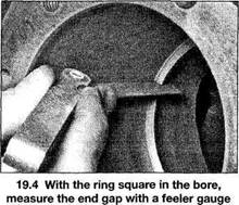
The ring must be square in the bore when checking the piston ring end gap
|
|
|
|
Typical bearing failures
2B•10 Engine removal and overhaul procedures
4 Dirt and other foreign particles get into the engine in a variety of ways. It may be left in the engine during assembly, or it may pass through filters or the PCV system. It may get into the oil, and from there into the bearings. Metal chips from machining operations and normal engine wear are often present. Abrasives are sometimes left in engine components after reconditioning, especially when parts are not thoroughly cleaned using the proper cleaning methods. Whatever the source, these foreign objects often end up embedded in the soft bearing material and are easily recognised. Large particles will not embed in the bearing and will score or gouge the bearing and journal. The best prevention for this cause of bearing failure is to clean all parts thoroughly and keep everything spotlessly clean during engine assembly. Frequent and regular engine oil and filter changes are also recommended.
5 Lack of lubrication (or lubrication breakdown) has a number of interrelated causes. Excessive heat (which thins the oil), overloading (which squeezes the oil from the bearing face) and oil leakage or throw off (from excessive bearing clearances, worn oil pump or high engine speeds) all contribute to lubrication breakdown. Blocked oil passages, which usually are the result of misaligned oil holes in a bearing shell, will also oil starve a bearing and destroy it. When lack of lubrication is the cause of bearing failure, the bearing material is wiped or extruded from the steel backing of the bearing. Temperatures may increase to the point where the steel backing turns blue from overheating.
6 Driving habits can have a definite effect on bearing life. Low speed operation in too high a
gear (lugging the engine) puts very high loads on bearings, which tends to squeeze out the oil film. These loads cause the bearings to flex, which produces fine cracks in the bearing face (fatigue failure). Eventually the bearing material will loosen in pieces and tear away from the steel backing. Short trip driving leads to corrosion of bearings because insufficient engine heat is produced to drive off the condensed water and corrosive gases. These products collect in the engine oil, forming acid and sludge. As the oil is carried to the engine bearings, the acid attacks and corrodes the bearing material.
7 Incorrect bearing installation during engine assembly will lead to bearing failure as well.
Tight-fitting bearings leave insufficient bearing oil clearance and will result in oil starvation.
Dirt or foreign particles trapped behind a bearing insert results in high spots on the bearing which lead to failure.
8 Do not touch any shell's bearing surfacewith your fingers during reassembly; there is a risk of scratching the delicate surface, or of depositing particles of dirt on it.
9 As mentioned at the beginning of this Section, the bearing shells should be renewed as a matter of course during engine overhaul; to do otherwise is false economy.
18 Engine overhaul -reassembly sequence
1 Before beginning engine reassembly, make sure you have all the necessary new parts, gaskets and seals as well as the following items on hand:
Common hand tools.
A 1/2-inch drive torque wrench. Piston ring installation tool.
Piston ring compressor.
Short lengths of rubber or plastic hose to fit over connecting rod bolts.
Feeler gauges. A fine-tooth file. New engine oil.
Engine assembly lube or moly-base grease.
Gasket sealant. Thread-locking compound.
2 In order to save time and avoid problems, engine reassembly must be done in the following general order:
Piston rings (Part B).
Crankshaft and main bearings (Part B).
Piston/connecting rod assemblies (Part B). Main (crankshaft) oil seal (Part A). Cylinder head and followers (Part A). Camshafts (Part A).
Oil pump (Part A).
Timing belt/chain and sprockets (Part A).
Timing covers (Part A).
Oil pick-up (Part A). Oil sump (Part A).
Intake and exhaust manifolds (Chapter 4A).
Cylinder head cover (Part A).
Flywheel/driveplate (Part A).
19 Piston rings -refitting

1 Before installing the new piston rings, the ring end gaps must be checked.
2 Lay out the piston/connecting rod assemblies and the new ring sets so the ring sets will be matched with the same piston and cylinder during the end gap measurement and engine assembly.
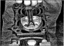
3 Insert the top (number one) ring into the first cylinder and square it up with the cylinder walls by pushing it in with the top of the piston
(see illustration). The ring should be near thebottom of the cylinder, at the lower limit of ring travel.
4 To measure the end gap, slip feeler gauges between the ends of the ring until a gauge equal to the gap width is found (see illustration). The feeler gauge should slidebetween the ring ends with a slight amount of drag. Compare the measurement to that found in this Chapter's Specifications. If the gap is larger or smaller than specified, double-check to make sure you have the correct rings before proceeding.
5 If the gap is too small (unlikely if genuine
Toyota parts are used), it must be enlarged, or the ring ends may contact each other during engine operation, causing serious damage. Ideally, new piston rings providing the correct end gap should be fitted. As a last resort, the end gap can be increased by filing the ring ends very carefully with a fine file. Mount the file in a vice equipped with soft jaws, slip the ring over the file with the ends contacting the file face, and slowly move the ring to remove material from the ends. Take care, as piston rings are sharp, and are easily broken.
6 Excess end gap isn't critical unless it's greater than the service limit listed in this Chapter's Specifications. Again, double-check to make sure you have the correct rings for your engine.
7 Repeat the procedure for each ring that will be installed in the first cylinder and for each ring in the remaining cylinders. Remember to keep rings, pistons and cylinders matched up.
8 Once the ring end gaps have been checked/ corrected, the rings can be installed on the pistons.
9 Fit the piston rings using the same technique as for removal. Fit the bottom (oil control) ring first, and work up. When fitting a three-piece oil control ring, first insert the expander, then fit the lower rail with its gap positioned 120° from the expander gap, then fit the upper rail with its gap positioned 120° from the lower rail. When fitting a two-piece oil control ring, first insert the expander, then fit the control ring with its gap positioned 180° from the expander gap.
Ensure that the second compression ring is fitted the correct way up, with its identification mark (either a dot of paint or the word TOP stamped on the ring surface) at the top,
Engine removal and overhaul procedures 2B•11
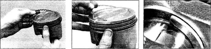
19.9a Fit the spacer/expander in the oil control ring groove
and the stepped surface at the bottom (see illustrations). Arrange the gaps of the top andsecond compression rings 120° either side of the oil control ring gap, but make sure that none of the rings gaps are positioned over the gudgeon pin hole. Note: Always follow any instructions supplied with the new piston ring sets - different manufacturers may specify different procedures. Do not mix up the top and second compression rings, as they have different cross-sections.

|
|
|
|
|
Дата добавления: 2014-12-23; Просмотров: 547; Нарушение авторских прав?; Мы поможем в написании вашей работы!