КАТЕГОРИИ:
Архитектура-(3434)Астрономия-(809)Биология-(7483)Биотехнологии-(1457)Военное дело-(14632)Высокие технологии-(1363)География-(913)Геология-(1438)Государство-(451)Демография-(1065)Дом-(47672)Журналистика и СМИ-(912)Изобретательство-(14524)Иностранные языки-(4268)Информатика-(17799)Искусство-(1338)История-(13644)Компьютеры-(11121)Косметика-(55)Кулинария-(373)Культура-(8427)Лингвистика-(374)Литература-(1642)Маркетинг-(23702)Математика-(16968)Машиностроение-(1700)Медицина-(12668)Менеджмент-(24684)Механика-(15423)Науковедение-(506)Образование-(11852)Охрана труда-(3308)Педагогика-(5571)Полиграфия-(1312)Политика-(7869)Право-(5454)Приборостроение-(1369)Программирование-(2801)Производство-(97182)Промышленность-(8706)Психология-(18388)Религия-(3217)Связь-(10668)Сельское хозяйство-(299)Социология-(6455)Спорт-(42831)Строительство-(4793)Торговля-(5050)Транспорт-(2929)Туризм-(1568)Физика-(3942)Философия-(17015)Финансы-(26596)Химия-(22929)Экология-(12095)Экономика-(9961)Электроника-(8441)Электротехника-(4623)Энергетика-(12629)Юриспруденция-(1492)Ядерная техника-(1748)
Set sof t output 3 active for 2s
|
|
|
|
Jump to 30
B · 2,min. 0
Set sof t output 2 active for 2s
Jump to 21
F120N15 Reduct. intv
F120N14 Max grnintv-2 00.1 00.1 00.1 00.1
-------------------------------- - ------------------------- ------------ -- --- - --- -------
()" F36PN20 Par-20 095 F16CN20 lns-18 06-00-021
)>::J F36PN21 Pa1-21 F16CN21 lns-19 12-24-002
z (/) F36PN22 Pcu-22 F16CN22 lns-20 01·000·00
0 --+-
;v () F36PN24 PaJ·24 095 F16CN24 l ns-22 07-18-000
20:
21: B •Ppt5)
22: Sk;fA > B
< c--+- r-"W"'nI""'C: n......c:
F16CN25 l ns-23 06-00-030
23: Jump to 30
 m (i3 F16CN26 lns-24 16-41-006
;v F16CN27 lns-25 14-31-002
F16CN28 lns-26 071· 9·000
F16CN29 lns-27 06-00-030
F16CN30 lns-28 12-24-003
"lJ
co
<0
'0
s_
'0
24 · B •Ppt6)
26: Sk;f A< B
8.7 Step 6 - Green wave graph
The last page of the coordinated solutions programming guide doesn’t refer to the controller configuration. It just refer to the green wave graph visualisation.
Open two or more coordinated configurations in one ITC-PC main window. Move to STEP 15 and click on ”Green wave graph page”.
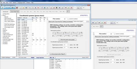
Figure 171: Green wave graph page
Decide the intersection location:

Figure 172: Intersection location
Define the main road signal groups for both intersections:
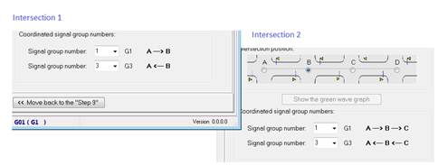
Figure 173: Main road signal group numbers
Click on the ”Show green wave graph” button.

Figure 174: ”Show green wave graph” button
Click on the ”Configurator” button (1), define distances and the travel speed in edit fields (2) and press the ”Refresh” button (3). Press the ”Configuration” button (1) again to hide the configuration panel.
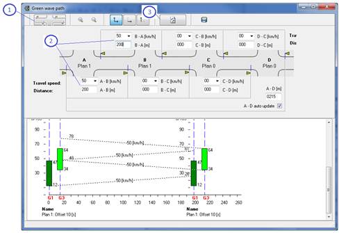
Figure 175: Configuration panel
The green wave graph represent two cycles. The picture contains:
- intersection names (1),
- coordinated group names (2),
- represented plan and respective offset time (3),
- coordinated signal groups green starting and ending points (4),
- approximate arrival points in [s] on the up and down stream junction (5).
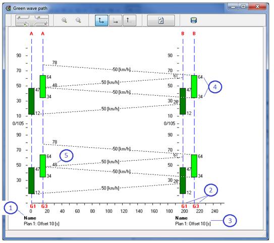
Figure 176: Green wave graph
8.8 Step 7 - Coordination configurations testing procedure
When testing coordination programming, firstly check if the current active plan is a ”coordi- nated” type. If you use the ITC-Sim software for testing coordination, make sure it runs in a real time speed mode (not the double speed).
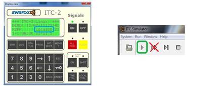
Figure 177: Plan type
You should also make sure that the time in all coordinated controllers is the same (specially in the Time Reference coordination based).
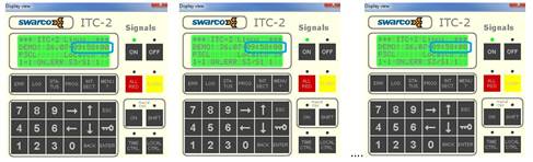
Figure 178: Checking the clock time
To set time in the controller press MENU-SERVICE-Set time (make sure the time in all controllers is exactly the same second by second):
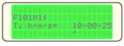
Figure 179: Set time menu
It is a good rule to check each configurations separately and only then check them all working together. If based on the time reference, the base cycle will be reset automatically. If based on impulse of synchronization, then we should simulate respective input in order to reset the base cycle in the right moment (once every cycle).
Checking base and internal cycle counters synchronization (cycles counters should be synchronized after the first cycle max with the second one):

Figure 180: Cycle counters status
1) First we have to check if the base and internal plan cycle counters are synchronized:
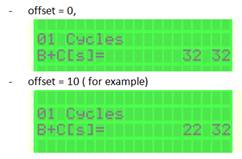
Figure 181: Cycle counters synchronization
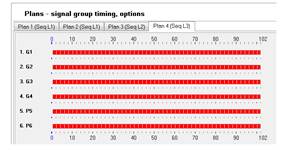
2) Once the base and plan cycle are synchronize, now you can check if the respective signal groups are synchronized (starts and ends green at the designed points).
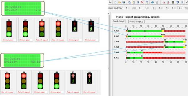
Figure 182: Signal group synchronization
3) When both the cycle and signal groups are synchronized, you can now check the coordina- tion in a real performance (running all configured controllers to see the green wave):
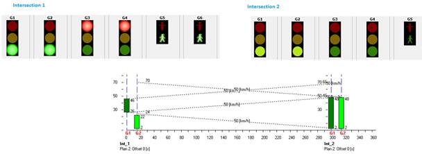
Figure 183: Green wave test
4) If something goes wrong it is always possible to check base coordination programming functions:
- F036 Plan parameter set checking:
The plan parameter set programming should represent starting and ending green stripe positions for each groups,
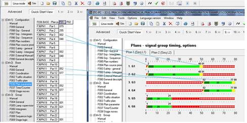
Figure 184: F036 Plan parameter set
- F016 CB control block:
Checking if the control block has been generated. It can be 1 or up to 4 CB generated.
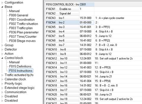
Figure 185: F016 CB control block
- Checking F012 Detector logic generation:
Each group should have some 3 detector logics generated for working in a local coordination.
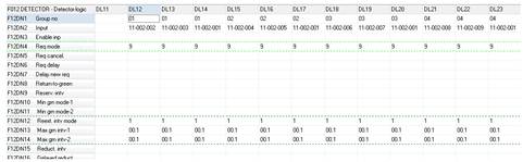
Figure 186: F012 Detector Logic
9 SPOT plan programming
When programming for SPOT, first you have to choose specific plan that will be triggered from the SPOT unit in centralized mode. The specified plan will be then modified together with its Sequence, Stage Logic and Action Table functions.
9.1 SPOT plan number
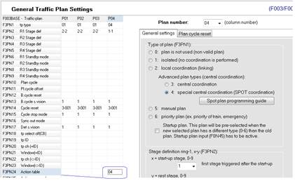
First, choose the plan from the list (2) that will be triggered from the SPOT unit in centralized mode and make it central coordinated type (3) (STEP 6). Add a new plan if necessary (1) (STEP 1).
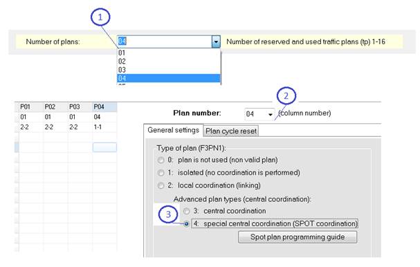
Figure 187: Central coordinated plan type
9.2 Auxiliary communication port
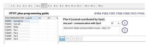
Press the ”SPOT plan programming guide” button in order to move to the SPOT plan program- ming wizard.
First choose ”Auxiliary equipment” column that will be programmed for the SPOT communica- tion protocol (1).
These parameters can be used to connect different equipment to the controller by using the standard RS-232 serial interface. Four auxiliary interfaces are available (A1-A4).
And follow suggestions from the comment field (2).
9.3 Step 1 - Communication
- first choose the com port number in to which the SPOT unit is going to be physically connected to the controller (1).
- set the communication speed (bit per second) (2) - it has to match the SPOT unit communi- cation settings,
- decide the software inputs range (3) that is going to be used in SPOT communication protocol to run signal groups

9.4 Step 2 - Sequence Logic number
Associate your SPOT with its own specific Sequence Logic. No other plans should be associated with the same Sequence Logic. Add a new Sequence Logic in STEP 1 if necessary.
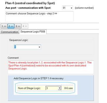
Figure 188: Sequence Logic number
You can move to the next step when the SPOT plan - Sequence Logic association is confirmed.
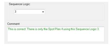
Figure 189: Sequence Logic number programming confirmed
9.5 Step 3 - Stage Logic number
Associate your SPOT with its own specific Stage Logic. No other plans should be associated with the same Stage Logic. Add a new Stage Logic in STEP 1 if necessary.
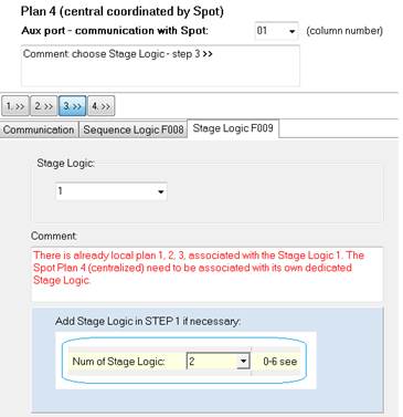
Figure 190: Stage Logic number
You can move to the next step when the SPOT plan - Stage Logic association is confirmed.
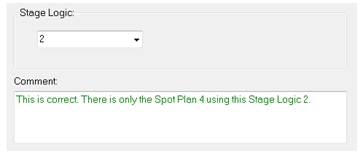
Figure 191: Stage Logic number programming confirmed
Whenever you are adding a new Sequence or Stage Logic in STEP 1, in order to get back to the SPOT programming guide, press the STEP 6 button (1), choose the SPOT plan from the list (2) and press the ”SPOT plan programming guide button” (3).
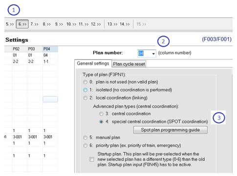
Figure 192: SPOT plan programming guide
9.6 Step 4 - SPOT programming
When all SPOT plan pre-programming steps 1-3 are ready, you can now press the ”Make Plan central coordinated” button in order to generate all necessary functions.
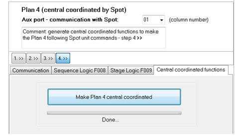
Figure 193: Generating SPOT plan functions
The software generates the following functions and modifications:
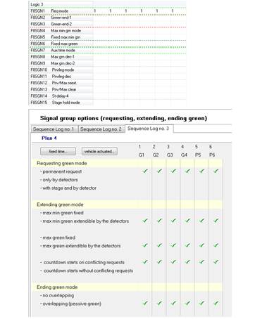
• clears all max green time programming from the SPOT plan (in central coordinated plan it is the SPOT unit deciding the green times and the controller should have this parameter empty),
• makes all groups requesting permanently in the associated Sequence Logic (this can be changed manually following the respective SPOT settings,
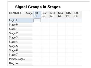
• clears all values from associated Stage Logic (in central coordinated plan it is the SPOT
unit creating stages and the controller should have this function empty)
• fills-in Action Definitions (F013) functions with the specific input definitions,
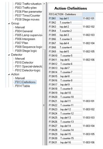
• creates Actions in the associated Action Table (F014) - usually column number equal to the SPOT plan number (press F4 button to see the comment line),
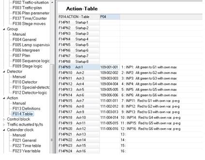
• associates Action Table with the SPOT plan
=<
|
|
|
, _,
 ::r
::r
<D
(-o/)
.I,
()
;:l
|
co (/)o
-as _,
 c 0 c
c 0 c
3.
"D::J

 SPOT unit F013
 Action-Definitions
F013ACTION -Definitions
F014
-
|
|
|
|
|
Дата добавления: 2014-12-23; Просмотров: 558; Нарушение авторских прав?; Мы поможем в написании вашей работы!