КАТЕГОРИИ:
Архитектура-(3434)Астрономия-(809)Биология-(7483)Биотехнологии-(1457)Военное дело-(14632)Высокие технологии-(1363)География-(913)Геология-(1438)Государство-(451)Демография-(1065)Дом-(47672)Журналистика и СМИ-(912)Изобретательство-(14524)Иностранные языки-(4268)Информатика-(17799)Искусство-(1338)История-(13644)Компьютеры-(11121)Косметика-(55)Кулинария-(373)Культура-(8427)Лингвистика-(374)Литература-(1642)Маркетинг-(23702)Математика-(16968)Машиностроение-(1700)Медицина-(12668)Менеджмент-(24684)Механика-(15423)Науковедение-(506)Образование-(11852)Охрана труда-(3308)Педагогика-(5571)Полиграфия-(1312)Политика-(7869)Право-(5454)Приборостроение-(1369)Программирование-(2801)Производство-(97182)Промышленность-(8706)Психология-(18388)Религия-(3217)Связь-(10668)Сельское хозяйство-(299)Социология-(6455)Спорт-(42831)Строительство-(4793)Торговля-(5050)Транспорт-(2929)Туризм-(1568)Физика-(3942)Философия-(17015)Финансы-(26596)Химия-(22929)Экология-(12095)Экономика-(9961)Электроника-(8441)Электротехника-(4623)Энергетика-(12629)Юриспруденция-(1492)Ядерная техника-(1748)
Action -Table 3 страница
|
|
|
|
Figure 305: STEP 10 - adding Sequence Logic
See: STEP 10 - Sequence Logic section 5.3 page 83
18.15 Step 14 Additional conditions
The sampled traffic logic requires some additional conditions: when P9 requests, P8 should get green too (even if not requesting). For this and other traffic conditions we can use the Detector Logic.
First, find empty Detector Logic. It is a good rule to leave one Detector Logic empty in order to distinguish ”physical input detectors” from ”logical input detectors”. In the following example that would be DL15.
Choose the signal group number from the list (1) - signal group that will be influenced by DL15.
And choose the input definition from the window (2) - when P9 is green, then request for green
in P8.
To learn more about different types of inputs see: Other input types section 5.2.12, page 79
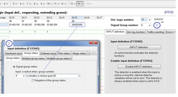
Figure 306: STEP 14 - additional DL
To learn more about different types of inputs see: Other input types section 5.2.12, page 79.
19 EXAMPLE II
19.1 Intersection layout
The interaction has 8 vehicle groups (V1, V2, V3, V4, V5, V6, V7 and V8).
There are 6 loop detectors (D1, D2, D3, D4, D5, D6) and 2 video detectors on direction V4 (C1, C2). Video detectors connect to the digital input terminal.
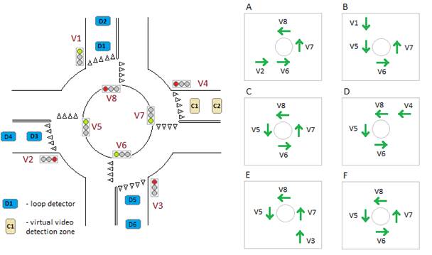
Figure 307: Intersection layout
The Stage Sequence contains both the main stages and sub stages stages (A, B, C, D, E, F).
19.2 Step 1 Intersection layout
First switch the graphical mode and type the intersection name, Backplane ID, number of signal groups, plans etc.
The configuration contains one ”dummy signal group” (non physical group 9). That is why there are 9 signal groups programmed in text edit (1) and 1 dummy group - text edit (2).
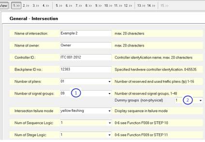
Figure 308: STEP 1
See: STEP 1 - Intersection layout section 4.1 page 18
19.3 Step 2 Signal groups
Click STEP 2 button and decide the signal groups name, type and min group sequence. The last signal group is a ”dummy group” (non physical group 9) - see label (1)
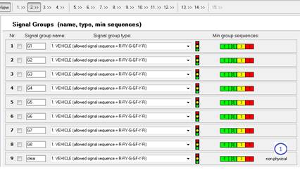
Figure 309: STEP 2
See: STEP 2 - Signal groups section 4.3 page 25
19.4 Step 3 Conflicts
Fill in the intergreen time matrix with the values from the traffic design. Values should always consider the local traffic regulations, speed and distances.
A ”Dummy group” (group 9) doesn’t need to be programmed for any physical conflicts.
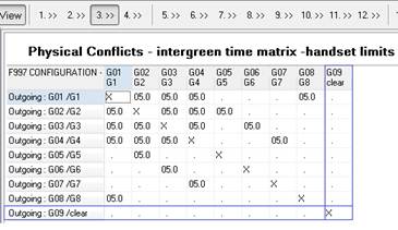
Figure 310: STEP 3
See: STEP 3 - Minimum inter green time matrix section 4.4 page 29
19.5 Step 4 Conflicting group numbers
Table from STEP 4 contains conflicting group numbers
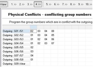
Figure 311: STEP 4
See: STEP 4 - Signal group conflicts section 4.4 page 31
19.6 Step 5 Start-up sequence
Choose start-up sequences from the list - different for the vehicle and pedestrian signal groups. A ”Dummy group” (group 9) stays dark in all three start-up intervals.
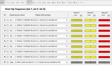
Figure 312: STEP 5
See: STEP 5 - Intersection start-up sequenc section 4.6 page 32
19.7 Step 6 General plan programming
Make the signal plans ”isolated type” and decide the star-up and rest stage. To learn more about:
- start-up stage definition see: Start-up stage section 4.7.3 page 34
- rest stage definition see: Rest stage programming section 6.1.1 page 89
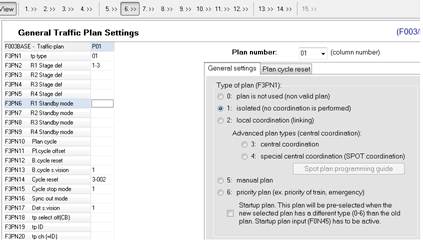
Figure 313: STEP 6
See: STEP 6 - General plan programming section 4.7 page 33
19.8 Step 7 Lamp supervision programming
See: STEP 7 - Lamp supervision section 4.8 page 36
19.9 Step 8 Intergreen time matrix
The Intergreen time marix from STEP 8 usually contains both the physical and logical conflicts - more about logical conflicts in section 4.9.2 page 41
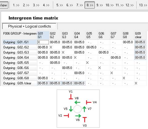
Figure 314: STEP 8
”Dummy group” (group 9) is in conflict against all ”external” vehicle groups (V1, V2, V3, V4). This way the ”clearing stage” can be easily defined in STEP 10. Whenever ”dummy group” gets green it is a clearing stage because non other ”external” vehicle groups can remain green together with ”dummy group”. Only the ”internal” vehicle groups (V5, V6, V7, V8) can be green together with ”dummy group” (group 9).
See: STEP 8 - Physical and fictive inter green time matrix section 4.9 page 40
19.10 Step 9 General plan programming
The plan drawing represents the traffic design. If your traffic design contains only the tabular representation of the green times, you can draw it on your own here in STEP 9. When drawing plan structure in STEP 9, consider both the green times and stage sequence.
The sample plan is based on using max green time in ”external” groups (V1, V2, V3, V4) and overlapping (passive green) for ”internal” groups (V5, V6, V7, V8). Thanks to the passive green plan gets its flexibility. It is sufficient enough to modify the green time in any of the external groups, in order to make the internal groups following the modifications right away.
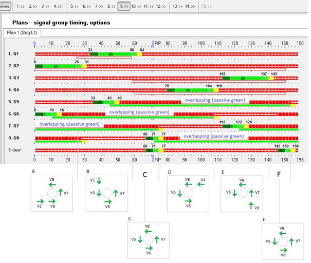
Figure 315: STEP 9
See: STEP 9 - Traffic plans programming section 4.10 page 43
Programming for the ”internal” signal groups (V5, V6, V7, V8) should be based on overlapping
(passive green):
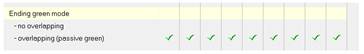
See: Requesting with stage and overlapping section 6.2.2 page 92
19.11 Step 11 Stage sequence
Clearing stage occurs twice in a cycle (stage 3 and 6). Clearing stages are based on a
”dummy group” (group 9) which is in conflict with all ”external” signal groups.
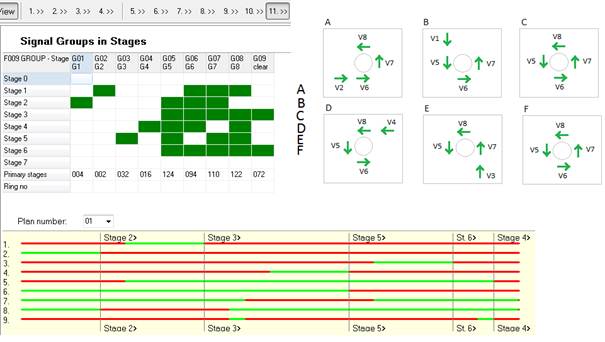
Figure 316: STEP 11
See: STEP 11 - Stage logic programming section 4.12 page 55
19.12 Step 13 Loop detector hardware programming
The software generates the default loop detector hardware programming.
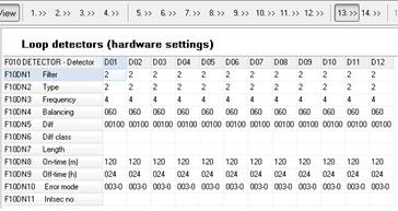
Figure 317: STEP 13
See: STEP 13 - Loop detectors section 5.1 page 66
19.13 Step 14 Detector Logic
The Detector Logic programming links loop and video detectors with vehicle groups:
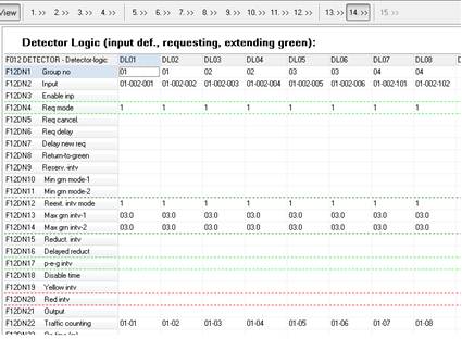
Figure 318: STEP 14
See: STEP 14 - Detector Logics section 5.2 page 68
19.14 Step 10 Sequence Logic programming
Press the ”vehicle actuated” button and change the default fixed time settings to vehicle ac- tuated.
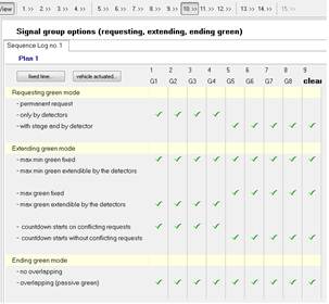
Figure 319: STEP 10
See: STEP 10 - Sequence Logic section 5.3 page 83
19.15 Step 14 Additional conditions
The sample traffic logic requires some additional conditions: clearing stage 3 should be requested only if both V1 and V2 were requesting green. Clearing stage 6 should occur only if both V3 and V4 were requesting green.
First find empty the Detector Logic. It is a good rule to leave one Detector Logic empty in order to distinguish ”physical input detectors” from ”logical input detectors”. In the following example that would be DL10.
Choose the signal group number from the list (1) - signal group that will be influenced by DL10.
And choose the input definition from the window (2) - Special detector 1.
Click on the ”Show Special detector function page...” link in order to define the Special detector 1.
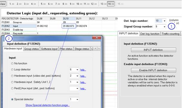
Figure 320: STEP 14 - additional DL
To learn more about different types of inputs see: Other input types section 5.2.12, page 79.
Click on the ”INPUT definition A” button (1), choose the ”Group status” input type page (3)
and define the input as active when group 1 ”has request in red”.
Click on the ”INPUT definition B” button (1), choose the ”Group status” input type page (3)
and define the input as active when group 2 ”has request in red”.
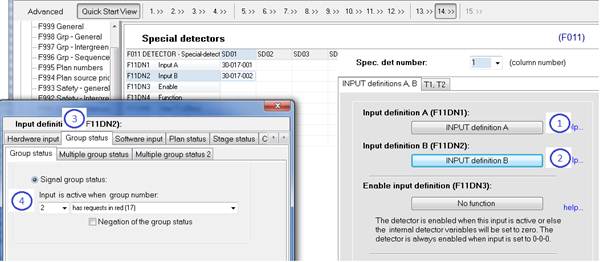
Figure 321: Special Detector programming
When both inputs A and B are defined, choose the special detector logic function (AND, OR
etc).
In the example below it is going to be function 6 (AND) - when group 1 ”has request in red”
AND group 2 ”has request in red” - Special detector 1 remains active.
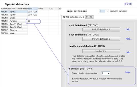
Figure 322: Special detector function
When Special Detector 1 remains active, DL10 requests for green for ”dummy group” (group 9)
in order to activate the ”clearing” stage 3.
When Special Detector 2 remains active, DL11 requests for green for ”dummy group” (group 9)
in order to activate the ”clearing” stage 6.

Figure 323: Special detector input type
If any additional conditions are required you can always use ”Enable INPUT definition” in the
Detector Logic programming. For example:
DL10 should be only considered when current stage number is smaller or equal 3. DL11 should be only considered when current stage number is greater or equal 3.
In order to define any additional conditions, click on the ”Enable INPUT definition” button and choose the specific input (condition).
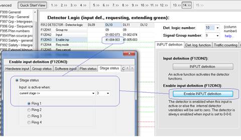
Figure 324: Enable INPUT definition
To learn more about different types of inputs see: Other input types section 5.2.12, page 79.
|
|
|
|
|
Дата добавления: 2014-12-23; Просмотров: 633; Нарушение авторских прав?; Мы поможем в написании вашей работы!