КАТЕГОРИИ:
Архитектура-(3434)Астрономия-(809)Биология-(7483)Биотехнологии-(1457)Военное дело-(14632)Высокие технологии-(1363)География-(913)Геология-(1438)Государство-(451)Демография-(1065)Дом-(47672)Журналистика и СМИ-(912)Изобретательство-(14524)Иностранные языки-(4268)Информатика-(17799)Искусство-(1338)История-(13644)Компьютеры-(11121)Косметика-(55)Кулинария-(373)Культура-(8427)Лингвистика-(374)Литература-(1642)Маркетинг-(23702)Математика-(16968)Машиностроение-(1700)Медицина-(12668)Менеджмент-(24684)Механика-(15423)Науковедение-(506)Образование-(11852)Охрана труда-(3308)Педагогика-(5571)Полиграфия-(1312)Политика-(7869)Право-(5454)Приборостроение-(1369)Программирование-(2801)Производство-(97182)Промышленность-(8706)Психология-(18388)Религия-(3217)Связь-(10668)Сельское хозяйство-(299)Социология-(6455)Спорт-(42831)Строительство-(4793)Торговля-(5050)Транспорт-(2929)Туризм-(1568)Физика-(3942)Философия-(17015)Финансы-(26596)Химия-(22929)Экология-(12095)Экономика-(9961)Электроника-(8441)Электротехника-(4623)Энергетика-(12629)Юриспруденция-(1492)Ядерная техника-(1748)
Key principles. Theme:active network equipment switches
|
|
|
|
PURPOSE OF THE WORK
LABORATORY WORK № 2
THEME: ACTIVE NETWORK EQUIPMENT SWITCHES
The study of construction and operation principles of local network switches.
In any node of a network where two and more communication lines converge and which is intermediate for data flow forwarding, such functions as switching, concentration, multiplexing and routing can be fulfilled. For their implementation in the node special equipment which is defined by the common concept «the active network equipment» is installed. The network equipment can perform one of the listed functions and correspondingly be named «switch", «hub", «router", or combine a number of functions (for example, the automatic telephone exchange fulfils the functions of concentration, switching, routing).
Application of either devices depends on the type of an organized network segment (a local area network, a territorial network), and also requirements for efficiency of a network, possibility of its growth (scaling) and reconfiguration (topology changes).
Today switches are the most widely used network devices when organizing local area networks because they completely satisfy the mentioned above requirements. The first switch for local area networks has appeared for Ethernet technology. The generalized block diagram of an Ethernet switch is shown in Fig. 2.2.1.
Each port is served by one processor of Ethernet – ЕРР (Ethernet Packet Processor) packages. Besides, the switch has the system unit which coordinates the operation of all ERR processors. The system unit carries out the common address table of the switch and provides control of switch operation.
For frames transmission between ports switching matrix such as in telephone switches or multiprocessor computers is used, connecting some processors with several memory modules. The switching matrix operates aster a circuit switching principle. For 8 ports the switching matrix can provide 8 simultaneous internal channels at a half-duplex operating mode of ports and 16 - at full-duplex mode when the transmitter and the receiver of each port work independently from each other.
With frame arrival in any port ERR processor buffers several first bytes of the frame to read the destination address. After reception of the destination address the processor makes the decision about package transmission, without waiting for the arrival of other frame bytes. For this purpose it analyzes its own cache (buffer memory) of the address table and if it does not find the necessary address there, it accesses to the system unit which works in the multitasking mode, way serving enquiries of all processors ERR parallely. The system unit makes review of the common address table and returns the found string to the processor which it buffers in its cache for the further use.
Figure 2.2.1 – General switch structure
When a destination address is found, ERR processor knows what is necessary to do with an arriving frame (during the review of a translation table the processor has been continuing buffering of frame bytes arriving in the port). If the frame needs to be filtered out, the processor simply stops writing down frame bytes in the buffer, clears the buffer and waits for the arrival of a new frame.
If it is necessary to transfer a frame to other port the processor accesses to a switching matrix and tries to install the path in it linking its port with a port through which there is a path to the destination address. The switching matrix is able to do this only in that case when the port of the destination address is idle, at this moment that is, it is not connected to the other port.
If the port is occupied, so as in any device with circuit switching, the matrix refuses the connection. In this case the frame is completely buffered by the processor of input port then the processor expects clearing an output port and derivation of the necessary path by a switching matrix.
When the necessary path is installed buffered bytes of a frame which are received by the processor of an output port are routed to it. As soon as the processor of an output port has access to Ethernet segment connected to it, frame bytes start to be transferred to a network at once. The processor of an input port constantly stores some bytes of a received frame in its buffer that allows it independently and asynchronously to receive and transfer frame bytes.
When an output port is idle while receiving a frame the delay between reception of the first frame byte by the switch and appearance of the same byte at the output of the destination address port makes up not more than 40 mcs.
The main reason of the productivity rise of a network at when the switch is used is parallel processing of several frames. Fig. 2.2.2 illustrates this effect.
Figure 2.2.2 – Parallel frames transmission by the switch
The common productivity of the switch in the given example will be 4x10 = 40 Mbit/s, and if an example for N ports is generalized it will be (N/2) x10 Mbit/s. It is said that the gives the selected capacity of the protocol (10 Mbit/s) to each server or a segment, connected to its ports.
If the port works in a half-duplex mode, for example Ethernet 10 Mbit/s productivity of port Cpi is equal 10 Mbit/s and if in full-duplex mode its Cpi will make 20 Mbit/s.
The internal arrangement of switches of various manufacturers sometimes differs very much, however the principle of parallel frames processing at each port remains the same.
Implementation of switching function in switches. Now switches use one of three circuits of input and output processors interaction:
- switching matrix;
- divided multiport memory;
- the common bus.
Often these three ways of interaction are combined in one switch.
Switches on the basis of switching matrix. The switching matrix is the main and the fastest way of interaction of port processors, it has been realized in the first industrial switch of local area networks. However, matrix implementation is possible only for certain number of ports, and besides complexity of the circuit increases proportionally to a square of quantity of switch ports (Fig. 2.2.3).
Figure 2.2.3 – Switching matrix
Switches with divided memory. The following base architecture of ports interaction – is two-input divided memory. The example of such architecture is shown in Fig. 2.2.4.
Input blocks of port processors are connected to a switched input of divided memory, and output blocks of the same processors are connected to a switched output of this memory. Switching of an input and an output of divided memory is controlled by the manager of queues of output ports. In the divided memory the manager organizes some queues of data, one by one for each output port. Input blocks of processors transfer enquiries for a data record to a queue of that port which corresponds to the address of package destination to the manager of ports. The manager in turn connects a memory input to one of the input blocks of processors and it copies a part of frame data to a queue of a certain output port. As far as queues are filled in, the manager also makes connection of an output of divided memory in twin to output blocks of port processors, and data from the queue are copied in to a processor output buffer.
Memory should be rapid enough to maintain data recording rate between N ports at the switch. Application of the common buffer memory that is distributed between separate ports by the manager flexible, reducing the requirements to the size of buffer memory of the port processor.
Figure 2.2.4 – The architecture of divided memory
Switches with the common bus. Switches with the common bus use the high-speed bus in the time division mode to link port processors. The bus is a passive element here, and the active role is fulfilled by port processors.
The example of such architecture is shown in Fig. 2.2.5. Not to be a switch drawback, bus productivity should be at least N/2 (where N is the number of ports) times higher than the speed of data arrival into output blocks of port processors. Besides, the frame should be transferred over the bus in small parts, by some bytes not to have frame transmission delays on the whole. The size of such data cell is defined by the manufacturer of the switch.
The processor input block places a tag in which the number of a port destination is specified, in a cell transferred over the bus. Each output block of the port processor has a filter of tags which selects the tags intended for the given port.
The bus as well as the switching matrix cannot perform intermediate buffering but as frame data are divided into small cells there aren’t delays with initial waiting for output port availability in this circuit.
Figure 2.2.5 – The common bus architecture
Combined switches. Each of the described architectures has advantages and disadvantages, therefore these architectures are often applied in a combination with each other in difficult switches.
Intelligent switches. Except its basic purpose to enhance links capacity, the switch allows to build network segments isolated at a logical level which information flows are not intersected, and also to control these flows and to manage them. A so called intelligent switch has these functions.
Organization of logically isolated network segments has received the name of virtual local area networks (Virtual LAN, VLAN) technology.
A group of network computers forming a segment which traffic is completely isolated from computers of other network segments is named a virtual network. At the same time within a virtual network frames are transferred according to the technology of switching, that is to that port which is linked to the destination address of a frame.
The technology of virtual networks allows reconfiguring a network flexibly (to change its topology) by means of a program, without resorting to physical network reconstruction.
Virtual networks can be intersected, if one or several computers are a part more than one virtual network.
In Fig. 2.2.6 server of e-mail is a part of 3 and 4 virtual networks. It means that its frames are transferred by switches to all computers included to these networks. If any computer is only a part of virtual network 3, then its frames will not reach network 4, but it can interact with computers of network 4 through the common mail server.
The technology of virtual networks is shown in IEEE 802.1Q standard which defines the basic rules of construction of virtual local area networks, link-layer protocol-independent. This link layer is supported by the switch.
When forming virtual networks on the basis of one switch the grouping mechanism in a network of switch ports (Fig. 2.2.7) is usually used. Thus each port is assigned to this or other virtual network. The frame which has arrived from a port, for example, belonging to virtual network 1, will never be transferred to a port which does not belong to this virtual network. The port can be assigned to several virtual networks though in practice it is seldom done, because the effect of complete isolation of networks disappears.
Grouping of ports for one switch is the most logical way of VLAN formation as virtual networks constructed on the basis of one switch cannot be more than ports. If the segment constructed on the basis of the hub is connected to one port then the nodes of such segment do not need to be included in different virtual networks because the traffic of these nodes will be common.
Figure 2.2.6 – Virtual networks
Creation of virtual networks on the basis of grouping of ports does not demand a great volume of manual operation from the manager it is enough to assign each port to one of the several in advance named virtual networks. Usually such operation is fulfilled by means of the special program applied to the switch. Performance of this procedure is provided in the given laboratory work.
Common description of FNSW–16/2400S PLANET switch. FNSW-16/2400S PLANET switch belongs to the class of intelligent switches. In a local area network of the laboratory of the Communication networks chair it performs the function of an access switch of a local segment which includes 10 computers. Using VLAN technology by means of ports grouping of this switch the specified segment can be divided into smaller network segments, without resorting to physical network sharing. It is very convenient in the case when it is necessary to organize fast networks for small user groups, each of which solves the independent task. These workgroups can organize an access to common information resources, having included a server at which they are concentrated in the structure of each group.
Figure 2.2.7 – Grouping of the switch ports
The front panel of the switch. The front panel of FNSW-16/2400S PLANET switchis presented in Fig. 2.2.8.

Figure 2.8 – Front panel of FNSW-16/2400S switch
Let's consider the assignment of ports. There are 16 ports of 100Base-TX standard (a copper cable a twisted pair, transmission bit rate 100 Mbit/s) with RJ-45 plugs and AUI of 100Base-FX standard (fiber optic cable) with a special plug for connection of the external transceiver in FNSW-16/2400S switch. By means of this port the switch is connected to the trunk cable connecting hubs between each other, or the connection of the computer which is more than on 500 m. far from the switch is provided.
The common port with RJ-45 plugs, intended for network adapter connection, is named MDI-X (cross-connect MDI). It has inverted bussing (cabling) of plug contacts that allows to connect workstation network adapter to the switch by means of a standard connective cable which doesn’t cross-connect.
In case of switches connection through the standard port with MDI-X it is as a rule necessary to use a non-standard cable with cross connection of pairs. To simplify this procedure the MDI-switch is provided in this switch, with its help MDI-X port is switched to MDI port which doesn’t have pairs cross-connect.
All 100Base-TX ports automatically provide the possibility of computers connection in a full-duplex mode. When a segment of several computers interconnected by a hub is linked to a port a half-duplex mode is switched on automatically. Data transmission rate through a port can be set up compulsorily through a console port if there is a need in it.
Cable. Switch ports provide possibility to connect a copper cable – 100Base-TX standard twisted pair and a common telephone cable of 10Base-T standard.
Indication. The green indicator on the front panel shows the device status – on/off. There is an indicator of the device connection, there which shows whether the device is connected to a fiber optic port. Each port has three indicators in its turn (see Table 2.2.1).
Table 2.2.1 – Indicator’s description
| Indicator | Color | Value | Description |
| Upper | Constant yellow | FDX | Operation in full-duplex mode |
| Blinking yellow | Col | Collision detected | |
| Middle | Constant green | Link | Presence of physical connection |
| Blinking green | Activity | Data reception | |
| Lower | Constant green | 100M | Port works at 100M bit rate |
| Blinking green | 10M | Port works at 10M bit rate |
The back panel of switch illustrated in Fig. 2.2.9
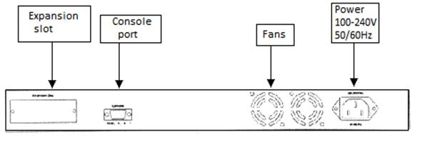
Figure 2.2.9 – Back panel of FNSW-16/2400S switch
Additional slot. The 16th port of the switch can be transformed to 100base-FX switch port. For this purpose it is necessary to install the additional unit in to an extension slot. If the unit is installed, then the 16th port on the front panel is switched of.
Power supply
Tolerable limit: from 100В to 240В, frequency: 50/60 HZ.
RS-232 console
RS-232 console is intended to manage the switch. To manage the switch by means of a personal computer it is necessary to connect one end of a cable (the cable is delivered together with the switch) to a console port of the switch, and another to СОМ1 or COM2 computer port.
FNSW-16/2400S switch setup. Connection to the PC. After the operations on connection of RS-232 console are fulfilled, it is necessary to start the remote access and Hyper Terminal control program (it goes in a standard configuration of Windows 9.x, 2000, NT) or РгоСОММ:
|
|
|
|
|
Дата добавления: 2014-12-27; Просмотров: 508; Нарушение авторских прав?; Мы поможем в написании вашей работы!