КАТЕГОРИИ:
Архитектура-(3434)Астрономия-(809)Биология-(7483)Биотехнологии-(1457)Военное дело-(14632)Высокие технологии-(1363)География-(913)Геология-(1438)Государство-(451)Демография-(1065)Дом-(47672)Журналистика и СМИ-(912)Изобретательство-(14524)Иностранные языки-(4268)Информатика-(17799)Искусство-(1338)История-(13644)Компьютеры-(11121)Косметика-(55)Кулинария-(373)Культура-(8427)Лингвистика-(374)Литература-(1642)Маркетинг-(23702)Математика-(16968)Машиностроение-(1700)Медицина-(12668)Менеджмент-(24684)Механика-(15423)Науковедение-(506)Образование-(11852)Охрана труда-(3308)Педагогика-(5571)Полиграфия-(1312)Политика-(7869)Право-(5454)Приборостроение-(1369)Программирование-(2801)Производство-(97182)Промышленность-(8706)Психология-(18388)Религия-(3217)Связь-(10668)Сельское хозяйство-(299)Социология-(6455)Спорт-(42831)Строительство-(4793)Торговля-(5050)Транспорт-(2929)Туризм-(1568)Физика-(3942)Философия-(17015)Финансы-(26596)Химия-(22929)Экология-(12095)Экономика-(9961)Электроника-(8441)Электротехника-(4623)Энергетика-(12629)Юриспруденция-(1492)Ядерная техника-(1748)
Introduction
BASIS OF EDs AUTOMATIC CONTROL
ELECTRIC MOTOR CHOICE
TRANSIENT PROCESSES IN ED
5.1 General characteristic
5.2 Classification of executive mechanisms depending on character of static moment of resistance (Ms)
5.3 Starting of DC motor with independent excitation to the main speed at one stage of starting rheostat
5.4 Starting of DC motor with independent excitation to the main speed at multistage of starting rheostat
5.5 Starting of DC motor with independent excitation taking into account electromagnetic transient process
5.6 Transient mode of dynamic braking of DC motor with independent excitation
5.7 Transient modes in ED with traditional asynchronous motors
6.1 Motor heating and cooling. Classification of ED operation modes depending on the character of load change
6.1.1 Enduring (long-term) rated mode (S1)
6.1.2 Short-term rated operation mode (S2)
6.1.3 Repeatedly short-term rated operation mode (S3)
6.1.4 Rated modes S4-S8
6.1.5 Load diagrams of EDs
6.1.6 Electric motor power calculation at enduring operation mode (S1) and at constant load
6.1.7 Electric motor power calculation at enduring operation mode (S1) and at different cyclic load
6.1.8 Definition of AM permissible energizing frequency with short-circuited rotor
7.1 Introduction
7.2 Representation and designation of electric schemes elements
7.3 Opened systems of automatic control
7.3.1 Automatic control principles in opened contactor-relay systems
7.3.2 DC motor control of starting in angular speed function
7.3.3 DC motor control of starting in current function
7.3.4 DC motor control of starting in time function
7.4 Closed systems of automatic control
7.4.1 Basis of automatic control
7.4.2 Basis of AC EDs automatic control
7.4.3 Servo ED
7.4.4 Basis of ED program control
List of references
All buildings, constructed by a person should be divided into two groups.
The 1st group. Buildings, which are not intended for mutual displacement (motion) of any parts respectively the others (temperature displacements aren`t included). There are houses, bridges, vessels, towers, etc.
The 2nd group. Buildings, which are having mutual displacement (motion) of any parts respectively the others. There are mechanisms and machines.
Modern machine device consists of many single machines, mechanisms, apparatuses, joints and details, executing different functions, and all they taken together realize definite work, untended for maintenance of certain manufacture process.
Any developed machine devices consist of three main parts:
- motor;
- transmission mechanism;
- actuator mechanism.
First two parts intended to drive the third part, i. e. actuator. So, first two parts represent the DRIVE.
More simple and old drive – is a muscular drive, which in certain varieties was preserved nowadays. For example, manual, footing, mounted and so on.
To change muscular drive a mechanical drive (wind energy and water using), almost so ancient as muscular, was occurred. Application of water wheels is known before 3000 years BC (China). Now mechanical drive is also widely used:
- steam, gas and water turbines;
- internal combustion engines;
- pneumatic engines;
- hydraulic engines and so on.
But now the basic type of drive is electric drive(ED), and its field of application is far more than of all other types.
There is such definition of electric drive.
Electric drive – is an electromechanical system, including electromotor, converting, transmission and control devices, intended for driving executive actuators of machines, and for control of this motion.
In some cases this system has not converting and transmission devices.
Modern EDs are characterized by high automatization level of its operation, thus providing possibility of ED operation in more optimal modes.
Structural diagram of automatic ED system is shown on the next figure.
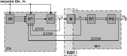
SD (ЗП) – setting device;
CD (КП) – control device;
PC (CП) – power converter (converting device);
M – electric motor (electromachine converter);
TD (ПП) – transmitting device;
AM (РО) – actuator mechanism;
FET, FMT (ДЗЗЭ, ДЗЗМ) – feedback electric (mechanical) transducer;
CS (СУ) – control system (includes power part PC and information part);
EMD (ЕДП) – electric motor device;
MP (МЧ) – mechanical transmitting deice (mechanical part) of ED;
IS, Us (Iм, Uм) – supply current and voltage of the motor;
 (
( ) – angular speed of actuator mechanism.
Electric energy, consumed from the main (independent power source) and having unregulated parameters IS, Us in PC power part of control system CS transforms into regulated one with parameters I,U and from there is supplied to electric motor M winding, where this energy transforms into mechanical power on motor shaft with angular speed ω. Mechanical energy is supplied from motor shaft to mechanical converter device, which transforms it with required parameters  .
.
This mechanical energy supplies to machine actuator mechanism AM. Control device CD realizes power converter PC control, receiving command signal from setting device SD and current information about ED and technological process, executed by ED by the help of feedback electric transducers FET or mechanical transducers FMT. By these transducers current, voltage, power of EM; enforces, speed, moment position of actuator mechanism (or another mechanical, electrical, thermal and so on) parameters transforms into proportional to these parameters electric signals. These signals inject into control device CD. In this device signals (i.e. information about ED current state and about technological process) are compared with set values (from setting device SD) and at presence of signal difference (signals from FET, FMT and signals from SD in control device CD) control signal generates and acts on power converter PC, which in turn acts on electric motor M by its changed parameters I, U in direction of difference removal. This removal exists for required accuracy and operation speed.
Thus, in structural diagram of ED we can separate three main parts:
- control system CS, consisting of power converting part PC and information part IP, including the next:
1) control device CD;
2) setting device SD;
3) feedback transducers system FTS;
4) protective, signal, indication elements (PSIE);
- electric motor device EMD, intended to transform electric energy into mechanical, or vice versa – mechanical into electrical one (electric motor can operate as motor and as generator);
- mechanical part (mechanical transmission device) – is MP, consisting of moving part of ED and of whole mechanical part MP from the motor to actuator mechanism AM; intended to transmit mechanical energy from the motor to actuator mechanism, or vice versa – from actuator mechanism AM to the motor M, and for transformation of motion character and motion parameters (speed, moment enforce and so on).
From mentioned above it is concluded that automated ED (except its main
ancient function of drive – to drive operating mechanism) also possesses control system, providing rational, optimal running of required operation mode.
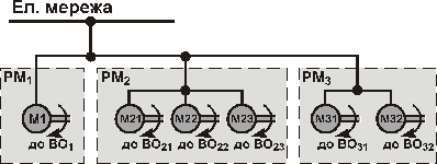
Electric drive was appeared in steam age, and at first its application replace steam machine, driving plant or shop transmission, by electric motor. Therefore, the first ED was the transmission drive.
Transmitting (group) electric drive. Here one motor M drives operative machine group or mechanisms of one operative machine by transmissions or other gears. The kinematic scheme of mechanical part is complex, bulky, and inefficient and now is rarely used.

On this and on two next figures it is accepted such conventional designations.
Ел. мережа – electric main;
We – electric energy;
Wм – mechanical energy;
OP (РМ) – operating machine;
EM (BO) – executive mechanism of operating machine.
Individual electric drive. Here each executive mechanism of operating machine is driving by one separate electric motor (individual single ED) or by several electric motors (multimotor ED).
|
|
Дата добавления: 2014-01-05; Просмотров: 558; Нарушение авторских прав?; Мы поможем в написании вашей работы!