КАТЕГОРИИ:
Архитектура-(3434)Астрономия-(809)Биология-(7483)Биотехнологии-(1457)Военное дело-(14632)Высокие технологии-(1363)География-(913)Геология-(1438)Государство-(451)Демография-(1065)Дом-(47672)Журналистика и СМИ-(912)Изобретательство-(14524)Иностранные языки-(4268)Информатика-(17799)Искусство-(1338)История-(13644)Компьютеры-(11121)Косметика-(55)Кулинария-(373)Культура-(8427)Лингвистика-(374)Литература-(1642)Маркетинг-(23702)Математика-(16968)Машиностроение-(1700)Медицина-(12668)Менеджмент-(24684)Механика-(15423)Науковедение-(506)Образование-(11852)Охрана труда-(3308)Педагогика-(5571)Полиграфия-(1312)Политика-(7869)Право-(5454)Приборостроение-(1369)Программирование-(2801)Производство-(97182)Промышленность-(8706)Психология-(18388)Религия-(3217)Связь-(10668)Сельское хозяйство-(299)Социология-(6455)Спорт-(42831)Строительство-(4793)Торговля-(5050)Транспорт-(2929)Туризм-(1568)Физика-(3942)Философия-(17015)Финансы-(26596)Химия-(22929)Экология-(12095)Экономика-(9961)Электроника-(8441)Электротехника-(4623)Энергетика-(12629)Юриспруденция-(1492)Ядерная техника-(1748)
Dynamic braking at independent excitation
|
|
|
|
If AM dynamic braking is realized by classical scheme then at AM deenergizing and closing stator circuit, the motor will make very small braking moment (emf will be small, since it is caused by residual magnetism because the main AM magnetic flux is generated by reactive stator current at it supplying from the main and the stator is deenergized).
For creation of needed braking moment it should to create at this a magnetic flux, supplying the direct current into the stator circuit on the braking moment, i.e. artificially create independent excitation on the braking time.
In general view scheme of independent excitation braking is shown on a figure:
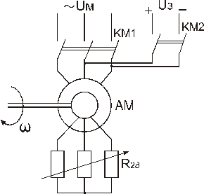
КМ1 is closed, КМ2 is opened – AM motor mode;
КМ1 is opened, КМ2 is closed – mode of AM dynamic braking.
Figure 3.44 – Scheme of dynamic braking at independent.
If AM will be phased, but not short-circuited at this, then additional active resistance  is connected onto rotor circuit. At regulation of it is possible to limit the rotor current and change the braking parameters.
We transform AM into generator with implicit poles by such switching, that operates at variable frequency. Rotor current is the load for such motor.
It is seen from a figure that switching of stator winding on direct current is asymmetrical. It is not possible to realize symmetrical switching of stator winding on a direct voltage without switching of phase windings of the stators. These windings are powered by the next way (look schemes a, b and c)
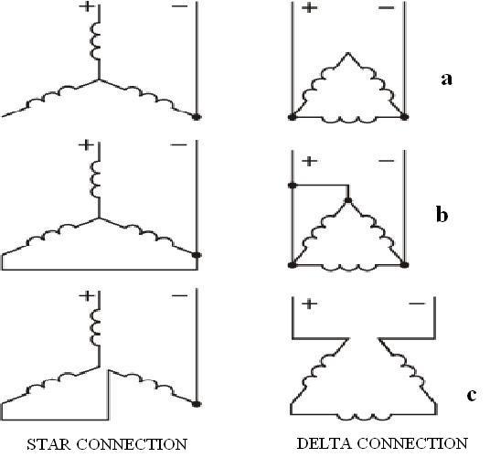
a – non-symmetrical scheme,
b – half-symmetrical scheme,
c – symmetrical scheme.
Figure 3.45 – Switching of AM stator winding on direct voltage.
Scheme a is the simplest where the less number of switching apparatuses is needed for switching on direct current. Disadvantage is that the load of separate phases is non-uniform.
Scheme b has a great number of contactors, but is more uniform.
In scheme c the load will be uniform, but it requires the most number of contacts. Scheme a is the most frequently used in practice because of its simplicity.
It shouldn`t forget that when supplying direct current the stator winding will have significantly less resistance as at alternating current supplying, because the resistance at DC supplying has only active component (and at AC it has both active and inductive component).

Figure 3.46 – Scheme of powering of AM stator winding at dynamic braking with independent excitation.
Excitation voltage  is significantly less then supply voltage
  at these conditions.
Static rectifier VD supplying from step-down transformer TV (mainly VD and unregulated TV) is most frequently used as the source of independent excitation at AM dynamic braking.
Direct current flowing by stator windings creates stationary in space magnetic flux where rotor at the expense of accumulated potential and kinetic energy of mechanism rotates. Emf is induced in rotor at this that determines the origination of rotor alternating current.
This current creates its stationary in space (in respect to stator) magnetic field.
In result of interaction of rotor current with stationary magnetic field braking moment is created. This moment value is related to three basic factors:
- stator magneto-motive force (excitation current);
- value of active resistance value in rotor circuit;
- rotor speed.
Mechanical characteristic of this braking moment are found in the 2nd quadrant. These resemble mechanical characteristics of motor mode by its shape.
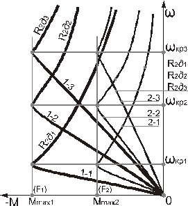
Figure 3.47 – Mechanical characteristic of dynamic braking with independent excitation.
All characteristics originate from the same point 0 ( ,
,  ) as the speed equals zero and
  .
.
Characteristics are presented for two values of stator mmf  and
and  and for three values of active resistance in rotor circuit [respectively for
  (
( );
);  (
( ) and
) and  , (
, ( )].
)].
The value of maximal braking moment is not related to resistance of armature circuit at set stator mmf (
 for and
  for ), but is related to the value of stator mmf.
Critical speed value (critical sliding), vice versa, is alike for one and the same value of rotor active resistance and doesn`t related to changing the value of stator mmf.
Likeness of mechanical characteristics of braking and motor modes is only visual. Their quantitative discrepancies are significant. With one and active rotor resistance critical sliding in motor mode is significantly higher then critical sliding of dynamic braking, since in dynamic mode alternating current of stator winding is absent. It means that inductive resistance  is absent, and only inductive magnetizing resistance
  which
which  is present. Then
 , and
, and
 ,
,  .
.
The second difference: in motor mode resulting AM mmf is rotational, and in braking mode mmf is stationary.
The third difference: stator current in motor mode is alternating, it describes the function of sliding, and at dynamic braking with independent excitation stator current is direct.
The fourth difference: all characteristics in motor mode originate from the point of maximal speed of motor mode that is synchronous ( ,
,  ), and in braking mode - from the point of minimal speed (, ).
Dynamic braking with independent excitation is widely used in electric drives (particularly in load-lifting machines).
|
|
|
|
|
Дата добавления: 2014-01-05; Просмотров: 547; Нарушение авторских прав?; Мы поможем в написании вашей работы!