КАТЕГОРИИ:
Архитектура-(3434)Астрономия-(809)Биология-(7483)Биотехнологии-(1457)Военное дело-(14632)Высокие технологии-(1363)География-(913)Геология-(1438)Государство-(451)Демография-(1065)Дом-(47672)Журналистика и СМИ-(912)Изобретательство-(14524)Иностранные языки-(4268)Информатика-(17799)Искусство-(1338)История-(13644)Компьютеры-(11121)Косметика-(55)Кулинария-(373)Культура-(8427)Лингвистика-(374)Литература-(1642)Маркетинг-(23702)Математика-(16968)Машиностроение-(1700)Медицина-(12668)Менеджмент-(24684)Механика-(15423)Науковедение-(506)Образование-(11852)Охрана труда-(3308)Педагогика-(5571)Полиграфия-(1312)Политика-(7869)Право-(5454)Приборостроение-(1369)Программирование-(2801)Производство-(97182)Промышленность-(8706)Психология-(18388)Религия-(3217)Связь-(10668)Сельское хозяйство-(299)Социология-(6455)Спорт-(42831)Строительство-(4793)Торговля-(5050)Транспорт-(2929)Туризм-(1568)Физика-(3942)Философия-(17015)Финансы-(26596)Химия-(22929)Экология-(12095)Экономика-(9961)Электроника-(8441)Электротехника-(4623)Энергетика-(12629)Юриспруденция-(1492)Ядерная техника-(1748)
Water Pump
|
|
|
|
COOLING SYSTEM 4-11
NOTE
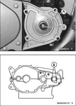
○The impeller and water pump shaft have a left-handed thread, therefore they must be turned clockwise [A] to remove.
• Shift the transmission into 1st gear.
While applying the rear brake, remove the impeller [B].
|
• Pull the water pump housing [A] and gasket out of the right crankcase. Turn the water pump shaft [B] clockwise, and remove it.
Water Pump Installation
• When installing the water pump shaft or impeller, shift the transmission into 1st gear and apply the rear brake.
• Apply silicone sealant to the area [A] where the mating surface of the crankcase contacts the water pump housing gasket.
Sealant - Kawasaki Bond (Silicone Sealant): 56019-120
• Apply high temperature grease to the lips of the water pump housing oil seal.
• Turn the water pump shaft or impeller counterclockwise, and tighten them.
Torque -Water Pump Shaft: 25 N-m (2.5 kgf-m, 18 ft-lb)
Water Pump Impeller: 9.8 N-m (1.0 kgf-m, 87 in-lb)
|
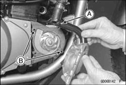
• Be sure to install the water pipe O-rings [A], and apply high temperature grease to them.
• Install the water pump cover with the water pipe, being careful of the two knock pins [B].
Torque-Water Pump Cover Bolts: 11 N-m (1.1 kgf-m, 95 in-lb)
|
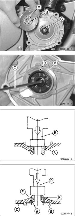
Mechanical Seal Inspection
• Visually inspect the mechanical seal.
• If any one of the parts is damaged, replace the mechanical seal as a unit.
OThe sealing seat and rubber seal may be removed easily by hand.
[A] Impeller Sealing Seat Surface
[B] Rubber Seal
[C] Mechanical Seal Diaphragm
Water Pump Housing Disassembly
|
|
|
|
|
Дата добавления: 2014-12-23; Просмотров: 379; Нарушение авторских прав?; Мы поможем в написании вашей работы!