КАТЕГОРИИ:
Архитектура-(3434)Астрономия-(809)Биология-(7483)Биотехнологии-(1457)Военное дело-(14632)Высокие технологии-(1363)География-(913)Геология-(1438)Государство-(451)Демография-(1065)Дом-(47672)Журналистика и СМИ-(912)Изобретательство-(14524)Иностранные языки-(4268)Информатика-(17799)Искусство-(1338)История-(13644)Компьютеры-(11121)Косметика-(55)Кулинария-(373)Культура-(8427)Лингвистика-(374)Литература-(1642)Маркетинг-(23702)Математика-(16968)Машиностроение-(1700)Медицина-(12668)Менеджмент-(24684)Механика-(15423)Науковедение-(506)Образование-(11852)Охрана труда-(3308)Педагогика-(5571)Полиграфия-(1312)Политика-(7869)Право-(5454)Приборостроение-(1369)Программирование-(2801)Производство-(97182)Промышленность-(8706)Психология-(18388)Религия-(3217)Связь-(10668)Сельское хозяйство-(299)Социология-(6455)Спорт-(42831)Строительство-(4793)Торговля-(5050)Транспорт-(2929)Туризм-(1568)Физика-(3942)Философия-(17015)Финансы-(26596)Химия-(22929)Экология-(12095)Экономика-(9961)Электроника-(8441)Электротехника-(4623)Энергетика-(12629)Юриспруденция-(1492)Ядерная техника-(1748)
Electrical system 16-65 fuses
|
|
|
|
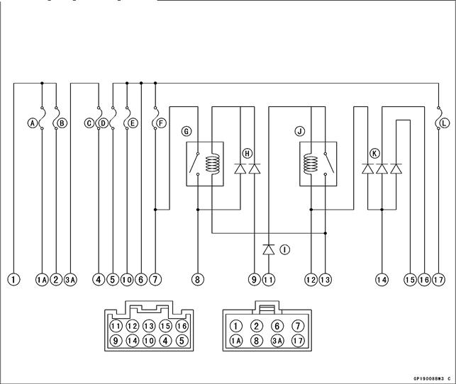
Junction Box Internal Circuit
Junction Box
ELECTRICAL SYSTEM
NOTE
Diode Circuit Inspection
Relay Circuit Inspection (with the battery connected)
| Battery Connection (+) (–) | Te s t e r Connection | Te s t e r Reading (Ω) | |
| Headlight Relay | 9 - 13 | 7-8 | |
| Starter Circuit Relay | 11 - 12 | (+) (-) 13 - 11 | Not ∞* |
(*): The actual reading varies with the hand tester used. (+): Apply tester positive lead. (–): Apply tester negative lead.
Diode Circuit Inspection
• Remove the left side cover (see Side Cover Removal in the Frame chapter).
• Remove the junction box.
• Check conductivity of the following pairs of terminals.
| Tester Connection | 13-8,13-9,12-11,12-14,15-14,16-14 |
•The resistance should be low in one direction and more than ten times as much in the other direction. If any diode shows low or high in both directions, the diode is defective and the junction box must be replaced.
OThe actual meter reading varies with the meter used and the individual diodes, but, generally speaking, the lower reading should be from zero to one half the scale.

A: Accessory Fuse 10 A B: Radiator Fan Fuse 10 A C: Turn Signal Relay Fuse 10 A D: Horn Fuse 10 A E: Ignition Fuse 10 A F: Headlight Fuse 10 A G: Headlight Relay H: Headlight Diodes I: Starter Diode J: Starter Circuit Relay K: Starter Lock Out Diodes L: Taillight Fuse 10 A
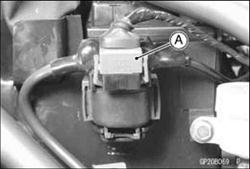
30 A Main Fuse Removal
• Remove the right side cover (see Side Cover Removal in the Frame chapter).
• Unlock the hook to lift up the lids of the main fuse cover [A].
• Pull up the main fuse cover with the starter relay connector.
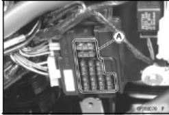
Junction Box Fuse Removal
• Remove the left side cover (see Side Cover Removal in the Frame chapter).
• Unlock the hook to lift up the lid from the junction box.
• Pull the fuses [A] straight up from the junction box with the nose plier.


|

|
Junction Box Fuse Installation
• If a fuse fails during operation, inspect the electrical system to determine the cause, and then replace it with a new fuse of proper amperage.
• Install the junction box fuses on the original position as specified on the lid.
Fuse Inspection
• Remove the fuse.
• Inspect the fuse element.
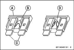
• If it is blown out, replace the fuse. Before replacing a blown fuse, always check the amperage in the affected circuit. If the amperage is equal to or greater than the fuse rating, check the wiring and related components for a short circuit.
Housing [A] Fuse Element [B] Terminals [C] Blown Element [D]
CAUTION
|
|
|
|
|
Дата добавления: 2014-12-23; Просмотров: 374; Нарушение авторских прав?; Мы поможем в написании вашей работы!