КАТЕГОРИИ:
Архитектура-(3434)Астрономия-(809)Биология-(7483)Биотехнологии-(1457)Военное дело-(14632)Высокие технологии-(1363)География-(913)Геология-(1438)Государство-(451)Демография-(1065)Дом-(47672)Журналистика и СМИ-(912)Изобретательство-(14524)Иностранные языки-(4268)Информатика-(17799)Искусство-(1338)История-(13644)Компьютеры-(11121)Косметика-(55)Кулинария-(373)Культура-(8427)Лингвистика-(374)Литература-(1642)Маркетинг-(23702)Математика-(16968)Машиностроение-(1700)Медицина-(12668)Менеджмент-(24684)Механика-(15423)Науковедение-(506)Образование-(11852)Охрана труда-(3308)Педагогика-(5571)Полиграфия-(1312)Политика-(7869)Право-(5454)Приборостроение-(1369)Программирование-(2801)Производство-(97182)Промышленность-(8706)Психология-(18388)Религия-(3217)Связь-(10668)Сельское хозяйство-(299)Социология-(6455)Спорт-(42831)Строительство-(4793)Торговля-(5050)Транспорт-(2929)Туризм-(1568)Физика-(3942)Философия-(17015)Финансы-(26596)Химия-(22929)Экология-(12095)Экономика-(9961)Электроника-(8441)Электротехника-(4623)Энергетика-(12629)Юриспруденция-(1492)Ядерная техника-(1748)
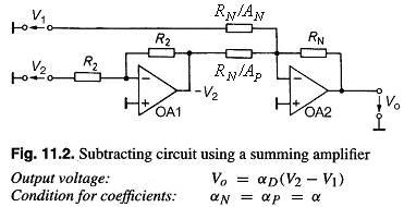
Subtracting Circuits
|
|
|
|
11.2.1. Reduction to an Addition
A subtraction operation can be reduced to the problem of an addition by inverting the signal to be subtracted. This requires the circuit shown in Fig. 11.2.
11.4. Integrators
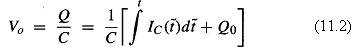
One of the most important applications of the operational amplifier in analog computing circuits is as an integrator. Its output voltage can be expressed in the general form
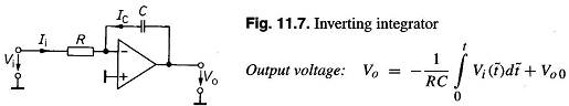
11.4.1. Inverting Integrator
The inverting integrator shown in Fig. 11.7 differs from the inverting amplifier in that the feedback resistor RN is replaced by the capacitor C. The output voltage is then expressed by
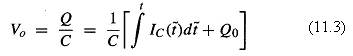
where Q0 is the charge on the capacitor at the beginning of the integration (t =0). As IC = -Vi/R, it follows:
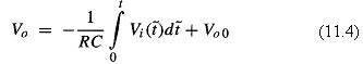
The constant Vo0 represents the initial condition: Vo0 = Vo (t = 0 ) = Q0/C.
11.4.2. Initial Condition
An integrator can often be used only if its output voltage Vo (t=0) can be set independently of the input voltage. Using the circuit shown in Fig. 11.10, it is possible to stop integration and set the initial condition.
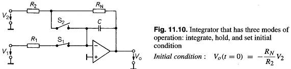
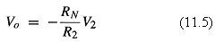
If the switch S1 is closed and S2 is open, the circuit operates like that in Fig. 11.7; the voltage V1 is integrated. If switch S1 is now opened, the charging current becomes zero in the case of an ideal integrator, and the output voltage remains at the value that it had at the time of switching. This may be of use if we want to interrupt computation; for example, in order to read the output voltage at leisure. To set the initial condition, S1 is left open and S2 is closed. The integrator becomes an inverting amplifier, with an output voltage of
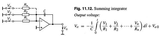
11.4.3. Summing Integrator
Just as the inverting amplifier can be extended to become a summing amplifier, so an integrator can be developed into a summing integrator as shown in Fig. 11.12. The relationship given for the output voltage can be derived directly by applying KCL to the summing point.
|
|
|
|
|
Дата добавления: 2014-01-11; Просмотров: 655; Нарушение авторских прав?; Мы поможем в написании вашей работы!