КАТЕГОРИИ:
Архитектура-(3434)Астрономия-(809)Биология-(7483)Биотехнологии-(1457)Военное дело-(14632)Высокие технологии-(1363)География-(913)Геология-(1438)Государство-(451)Демография-(1065)Дом-(47672)Журналистика и СМИ-(912)Изобретательство-(14524)Иностранные языки-(4268)Информатика-(17799)Искусство-(1338)История-(13644)Компьютеры-(11121)Косметика-(55)Кулинария-(373)Культура-(8427)Лингвистика-(374)Литература-(1642)Маркетинг-(23702)Математика-(16968)Машиностроение-(1700)Медицина-(12668)Менеджмент-(24684)Механика-(15423)Науковедение-(506)Образование-(11852)Охрана труда-(3308)Педагогика-(5571)Полиграфия-(1312)Политика-(7869)Право-(5454)Приборостроение-(1369)Программирование-(2801)Производство-(97182)Промышленность-(8706)Психология-(18388)Религия-(3217)Связь-(10668)Сельское хозяйство-(299)Социология-(6455)Спорт-(42831)Строительство-(4793)Торговля-(5050)Транспорт-(2929)Туризм-(1568)Физика-(3942)Философия-(17015)Финансы-(26596)Химия-(22929)Экология-(12095)Экономика-(9961)Электроника-(8441)Электротехника-(4623)Энергетика-(12629)Юриспруденция-(1492)Ядерная техника-(1748)
Cylinder, Piston. • Lap the valve to the seat, once t
|
|
|
|
ENGINE TOP END
Valves
ENGINE TOP END 5-31
Valves
ENGINE TOP END
|
• Lap the valve to the seat, once the seat width and O.D.
are within the ranges specified above.
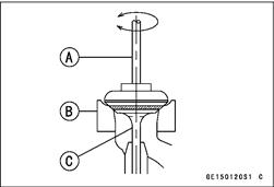
OPut a little coarse grinding compound on the face of the valve in a number of places around the valve head.
OSpin the valve against the seat until the grinding compound produces a smooth, matched surface on both the seat and the valve.
ORepeat the process with a fine grinding compound.
[A] Lapper
[B] Valve Seat
[C] Valve
• The seating area should be marked about in the middle of the valve face.
• If the seat area is not in the right place on the valve, check to be sure the valve is the correct part. If it is, it may have been refaced too much; replace it.
• Be sure to remove all grinding compound before assembly.
• When the engine is assembled, be sure to adjust the valve clearance (see Valve Clearance Adjustment in the Periodic Maintenance chapter).
|
|
|
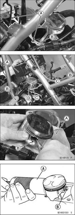
| Cylinder Removal • Remove the cylinder head (see Cylinder Head Removal). • Remove the main oil pipe mounting bolt. • Remove the bolts [A] and pull out the water pipe with water pump cover [B] (see water pump removal in the Cooling System chapter). • Take out the cylinder block so as not to damage the main oil pipe. |
Cylinder Installation
• Install:
Dowel Pins [A]
New Cylinder Base Gasket [B] OInstall the cylinder base gasket so that the swallen groove come to upper side.
• Apply molybdenum disulfide oil to the cylinder bore.
• Position the crankshaft so that all the piston heads are almost level.
• Install the cylinder block [A].
Special Tool - Piston Ring Compressor Grip: 5700-1095
[B] Piston Ring Compressor Belt, 067 ~ 079:
5700-1097 [C] Piston Base, 02.3: 5700-1336 [D]
OInsertthe piston rings with yourthumbs, if the special tools are not available.
Piston Removal
• Remove the cylinder (see Cylinder Removal).
• Wrap a clean cloth [A] around the base of each piston to secure it in position for removal and so that no parts and dirt will fall into the crankcase.
• Remove the piston pin snap rings [B] from the outside of each piston.
• Remove the piston by pushing its piston pin puller out the side from which the snap ring was removed. Use a piston pin puller, if the pin is tight.
Special Tool - Piston Pin Puller Assembly: 57001-910 [A]
|
|
|
|
|
Дата добавления: 2014-12-23; Просмотров: 403; Нарушение авторских прав?; Мы поможем в написании вашей работы!