КАТЕГОРИИ:
Архитектура-(3434)Астрономия-(809)Биология-(7483)Биотехнологии-(1457)Военное дело-(14632)Высокие технологии-(1363)География-(913)Геология-(1438)Государство-(451)Демография-(1065)Дом-(47672)Журналистика и СМИ-(912)Изобретательство-(14524)Иностранные языки-(4268)Информатика-(17799)Искусство-(1338)История-(13644)Компьютеры-(11121)Косметика-(55)Кулинария-(373)Культура-(8427)Лингвистика-(374)Литература-(1642)Маркетинг-(23702)Математика-(16968)Машиностроение-(1700)Медицина-(12668)Менеджмент-(24684)Механика-(15423)Науковедение-(506)Образование-(11852)Охрана труда-(3308)Педагогика-(5571)Полиграфия-(1312)Политика-(7869)Право-(5454)Приборостроение-(1369)Программирование-(2801)Производство-(97182)Промышленность-(8706)Психология-(18388)Религия-(3217)Связь-(10668)Сельское хозяйство-(299)Социология-(6455)Спорт-(42831)Строительство-(4793)Торговля-(5050)Транспорт-(2929)Туризм-(1568)Физика-(3942)Философия-(17015)Финансы-(26596)Химия-(22929)Экология-(12095)Экономика-(9961)Электроника-(8441)Электротехника-(4623)Энергетика-(12629)Юриспруденция-(1492)Ядерная техника-(1748)
CAUTION. Always install a new oil seal when the clutch release shaft is removed
|
|
|
|
Clutch
CLUTCH
NOTE
Clutch
CLUTCH 6-11
Always install a new oil seal when the clutch release shaft is removed.
CAUTION
| CAUTION |
| When inserting the release shaft, be careful not to remove the spring of the oil seal. |
• Apply high temperature grease to the oil seal lips in the clutch cover.
• Apply engine oil to the bearings in the hole of the clutch cover.
• Apply engine oil to the release shaft.
• Turning the release lever toward the rear, insert the release shaft straight into the hole of the clutch cover.
|
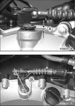
• Install the clutch inner cable tip in the release lever.
• Turn the release lever clockwise until it becomes hard to turn.
○The release lever should have proper clearance and angle as shown.
1 ∼ 3 mm
80° ∼ 90°
|
Clutch Removal
• Drain the engine oil (see Engine Oil Change in the Periodic Maintenance chapter).
• Remove the clutch cover (see Clutch Cover Removal).
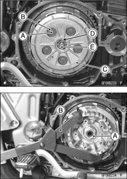
• Remove the clutch spring bolts [A], washers [B] and springs.
• Remove the clutch spring plate [C] with the thrust ball bearing [D] and pusher [E]. Remove the friction plates and steel plates.
• When loosening the clutch hub self-locking nut [A], use the clutch holder [B] to keep the clutch hub from turning as shown.
Special Tool - Clutch Holder: 57001-1243
Remove the clutch hub self-locking nut and washer.
|
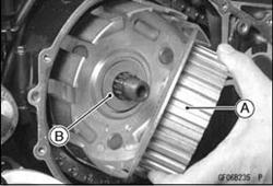
• Pull out the clutch hub [A] and thrust washer [B].
○The clutch housing can not be removed without major disassembly work (see Crankshaft/Transmission chapter).
Clutch Installation
• Install the thrust washer and clutch hub.
• Install the washer.
• Discard the used clutch hub self-locking nut, and install a new self-locking nut with the projected side facing outward.
• Install the clutch holder to keep the clutch hub from turning and tighten the clutch hub self-locking nut.
Special Tool - Clutch Holder: 57001-1243
Torque - Clutch Hub Nut: 132 N-m (13.5 kgf-m, 98 ft-lb)
• Install the friction plates and steel plates, starting with a
friction plate and alternating them.
|
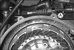
○The grooves [A] on the friction plate surfaces are cut tan-gentially and radially, install the friction plates so that the grooves run toward the center in the direction of the clutch housing rotation (counterclockwise viewed from the engine right side).
If new dry steel plates and friction plates are installed, apply engine oil to the surfaces of each plate to avoid clutch plate seizure.
|

|
• Apply engine oil to the thrust ball bearing.
• Apply molybdenum disulfide grease to the rubbing portion of clutch spring plate pusher.
• Tighten the clutch spring bolts.
Torque -Clutch Spring Bolts: 9.3 N·m (0.95 kgf·m, 82 in·lb)
Clutch Plate Wear, Damage Inspection
• Visually inspect the friction and steel plates for signs of seizure, overheating (discoloration), or uneven wear.
• If any plates show signs of damage, replace the friction plates and steel plates as a set.
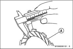
• Measure the thickness of the friction plate [A] at several points.
• If any of the measurements is less than the service limit, replace the friction plate.
Friction Plate Thickness
Standard: 2.9 ~ 3.1 mm (0.114 ~ 0.122 in.)
Service Limit: 2.75 mm (0.1082 in.)
Clutch Plate Warp Inspection
• Place each friction plate or steel plate on a surface plate, and measure the gap between the surface plate [A] and each friction plate or steel plate [B] with a thickness gauge [C]. The gap is the amount of friction or steel plate warp.
• If any plate is warped over the service limit, replace it with a new one.
Friction and Steel Plate Warp
Standard: less than 0.2 mm (0.008 in.)
Service Limit: 0.3 mm (0.012 in.)
|
|
|
|
|
Дата добавления: 2014-12-23; Просмотров: 405; Нарушение авторских прав?; Мы поможем в написании вашей работы!