КАТЕГОРИИ:
Архитектура-(3434)Астрономия-(809)Биология-(7483)Биотехнологии-(1457)Военное дело-(14632)Высокие технологии-(1363)География-(913)Геология-(1438)Государство-(451)Демография-(1065)Дом-(47672)Журналистика и СМИ-(912)Изобретательство-(14524)Иностранные языки-(4268)Информатика-(17799)Искусство-(1338)История-(13644)Компьютеры-(11121)Косметика-(55)Кулинария-(373)Культура-(8427)Лингвистика-(374)Литература-(1642)Маркетинг-(23702)Математика-(16968)Машиностроение-(1700)Медицина-(12668)Менеджмент-(24684)Механика-(15423)Науковедение-(506)Образование-(11852)Охрана труда-(3308)Педагогика-(5571)Полиграфия-(1312)Политика-(7869)Право-(5454)Приборостроение-(1369)Программирование-(2801)Производство-(97182)Промышленность-(8706)Психология-(18388)Религия-(3217)Связь-(10668)Сельское хозяйство-(299)Социология-(6455)Спорт-(42831)Строительство-(4793)Торговля-(5050)Транспорт-(2929)Туризм-(1568)Физика-(3942)Философия-(17015)Финансы-(26596)Химия-(22929)Экология-(12095)Экономика-(9961)Электроника-(8441)Электротехника-(4623)Энергетика-(12629)Юриспруденция-(1492)Ядерная техника-(1748)
Crankshaft Side Clearance
|
|
|
|
Standard: 0.05 ∼ 0.25 mm (0.0020 ∼ 0.0098 in.)
Service Limit: 0.40 mm (0.0157 in.)
CRANKSHAFT/TRANSMISSION 9-23 Balancer
|
Balancer Removal
• Split the crankcase (see Crankcase Splitting).
• Pull the balancer shaft with the balancer gear out of the crankcase.
Balancer Installation
• Apply oil to the inside of the balancer shaft bearing insert.
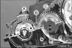
• Align the timing mark [B] on the balancer gear [A] with the timing mark [B] on the balancer drive gear [C] of the crankshaft.
• Assemble the crankcase (see Crankcase Assembly).
Balancer Shaft Bearing Insert/Journal Clearance
• Measure the bearing insert/journal clearance using a plastigage.
OSplit the crankcase and wipe each bearing insert and journal surface clean of oil.
OCut strips of plastigage to bearing insert width, and place a strip on each journal parallel to the balancer shaft so that the plastigage will be compressed between the journal and the bearing insert.
OInstall the lower crankcase half, and tighten the case bolts to the specified torque.
Torque - Crankcase 8 mm Bolts: 27 N-m (2.8 kgf-m, 20 ft-lb) Crankcase 6 mm Bolts: 12 N-m (1.2 kgf-m, 104 in-lb)
|
|
|
|
|
|
Дата добавления: 2014-12-23; Просмотров: 385; Нарушение авторских прав?; Мы поможем в написании вашей работы!