КАТЕГОРИИ:
Архитектура-(3434)Астрономия-(809)Биология-(7483)Биотехнологии-(1457)Военное дело-(14632)Высокие технологии-(1363)География-(913)Геология-(1438)Государство-(451)Демография-(1065)Дом-(47672)Журналистика и СМИ-(912)Изобретательство-(14524)Иностранные языки-(4268)Информатика-(17799)Искусство-(1338)История-(13644)Компьютеры-(11121)Косметика-(55)Кулинария-(373)Культура-(8427)Лингвистика-(374)Литература-(1642)Маркетинг-(23702)Математика-(16968)Машиностроение-(1700)Медицина-(12668)Менеджмент-(24684)Механика-(15423)Науковедение-(506)Образование-(11852)Охрана труда-(3308)Педагогика-(5571)Полиграфия-(1312)Политика-(7869)Право-(5454)Приборостроение-(1369)Программирование-(2801)Производство-(97182)Промышленность-(8706)Психология-(18388)Религия-(3217)Связь-(10668)Сельское хозяйство-(299)Социология-(6455)Спорт-(42831)Строительство-(4793)Торговля-(5050)Транспорт-(2929)Туризм-(1568)Физика-(3942)Философия-(17015)Финансы-(26596)Химия-(22929)Экология-(12095)Экономика-(9961)Электроника-(8441)Электротехника-(4623)Энергетика-(12629)Юриспруденция-(1492)Ядерная техника-(1748)
Transmission. Balancer Shaft Bearing Insert Selection
Balancer Shaft Bearing Insert Selection
Crankcase Bearing Bore Diameter Marks
NOTE
Balancer Shaft Diameter Marks
None: 27.987 ~ 27.993 mm (1.1019 ~ 1.1021 in.)
O: 27.994 ~ 28.000 mm (1.1021 ~ 1.1024 in.)
Л: Balancer Shaft Journal Diameter Marks, "O" mark or no mark.
• Put the lower crankcase half on the upper crankcase half without bearing inserts, and tighten the case bolts to the specified torque and sequence (see Crankcase Assembly).
• Measure the crankcase bearing bore diameter for the balancer shaft, and mark the upper crankcase half in accordance with the bore diameter.
OThe mark already on the upper crankcase half should almost coincide with the measurement.
O: 31.008 ~ 31.016 mm (1.2208 ~ 1.2211 in.)
None: 31.017 ~ 31.024 mm (1.2211 ~ 1.2214 in.)
DO: Crankcase Bearing Bore Diameter Marks, "O" mark or no mark.
No. 1 Journal
No. 2 Journal
• Select the proper bearing insert in accordance with the combination of the crankcase and the balancer shaft coding.
• Install the new inserts in the crankcase and check insert/journal clearance with a plastigage.
| Crankcase Main Bearing Bore Diameter Mark | Crankshaft Main Journal Diameter Mark | Bearing Insert* | ||
| Size Color | Part Number | |||
| L.H. | R.H. | |||
| О | о | Brown | 92028-1497 | 92028-1692 |
| None | None | Blue | 92028-1495 | 92028-1690 |
| о | None | Black | 92028-1496 | 92028-1691 |
| None | о |
CRANKSHAFT/TRANSMISSION 9-25

|
External Shift Mechanism Removal • Remove:
Left Front Footpeg
Shift Pedal Link Lever
Engine Sprocket (see Engine Sprocket Removal in the
Final Drive chapter)
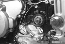
Chain Guard [A]
Neutral Switch Lead Connector [B]

|
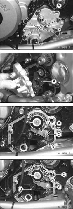
• Place an oil pan beneath the external shift mechanism cover [A]. Remove the external shift mechanism cover bolts [B].
• Pull the cover.
• Remove the cover with the shift shaft assembly while pushing the shift mechanism arm [A] down..
• Remove the nut [A] and take off the gear positioning lever [B] The lever has a collar [C], spring [D], and washer.
External Shift Mechanism Installation OThe small diameter side of the collar in the gear positioning lever must face toward the crankcase.
• Tighten the positioning lever nut [A].
Torque - Gear Positioning Lever Nut: 11 N-m (1.1 kgf-m, 95 in-lb)
• Check that the return spring pin [B] is not loose.
• If it is loose, remove it, apply a non-permanent locking agent to the threads, and tighten it.
Torque - Return Spring Pin: 20 N-m (2.0 kgf-m, 14.5 ft-lb)
• Apply silicone sealant to the area [C].
Sealant - Kawasaki Bond (Silicone Sealant): 56129-120
Replace the cover gasket with a new one.
9-26 CRANKSHAFT/TRANSMISSION
|
|
Дата добавления: 2014-12-23; Просмотров: 365; Нарушение авторских прав?; Мы поможем в написании вашей работы!