КАТЕГОРИИ:
Архитектура-(3434)Астрономия-(809)Биология-(7483)Биотехнологии-(1457)Военное дело-(14632)Высокие технологии-(1363)География-(913)Геология-(1438)Государство-(451)Демография-(1065)Дом-(47672)Журналистика и СМИ-(912)Изобретательство-(14524)Иностранные языки-(4268)Информатика-(17799)Искусство-(1338)История-(13644)Компьютеры-(11121)Косметика-(55)Кулинария-(373)Культура-(8427)Лингвистика-(374)Литература-(1642)Маркетинг-(23702)Математика-(16968)Машиностроение-(1700)Медицина-(12668)Менеджмент-(24684)Механика-(15423)Науковедение-(506)Образование-(11852)Охрана труда-(3308)Педагогика-(5571)Полиграфия-(1312)Политика-(7869)Право-(5454)Приборостроение-(1369)Программирование-(2801)Производство-(97182)Промышленность-(8706)Психология-(18388)Религия-(3217)Связь-(10668)Сельское хозяйство-(299)Социология-(6455)Спорт-(42831)Строительство-(4793)Торговля-(5050)Транспорт-(2929)Туризм-(1568)Физика-(3942)Философия-(17015)Финансы-(26596)Химия-(22929)Экология-(12095)Экономика-(9961)Электроника-(8441)Электротехника-(4623)Энергетика-(12629)Юриспруденция-(1492)Ядерная техника-(1748)
The various hoses should be marked to ensure correct refitting
|
|
|
|
Non-VVT-i engines
Removal
Intake manifold - removal and refitting

Note: If the intake manifold is to be unboltedonly for removal of the cylinder head, then the intake manifold can simply be unbolted from the cylinder head and pushed toward the bulkhead, without disconnecting any hoses, wires or linkage. The following procedure is for complete removal of the manifold from the vehicle.
1 Remove the throttle body as described in
Section 12.
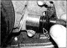
| 12.90 Undo the bolt (arrowed) and remove | 12.93 The crankshaft position sensor is | 12.97 Undo the bolt and pull the sensor |
| the crankshaft position sensor | located adjacent to the crankshaft pulley | from the timing chain cover. Renew the |
| (arrowed) | O-ring (arrowed) |
Fuel and exhaust systems 4A•13
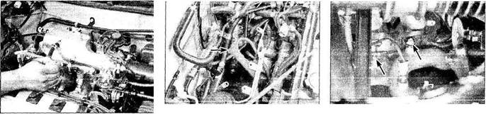
2 Label and detach the PCV and vacuum hoses connected to the intake manifold, including those from the vacuum sensor, vacuum servo unit and the air conditioning idle-up actuator - where fitted (see illustration).
3 The intake manifold can be removed with the injectors and fuel rail in place. If the injectors are to be removed from the intake manifold, refer to Section 12.
4 Disconnect the idle speed control valve electrical connector and the hoses from the air pipe at the rear of the manifold.
13.5 From underneath the vehicle, remove 13.6a Unbolt the wiring harness (right the bolt retaining this brace (arrowed) to arrow), then remove the lower manifold bolts the intake manifold
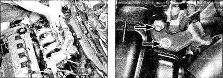
5 Unbolt the upper end of the intake manifold-to-block brace (accessible from under the vehicle), and the upper manifold brace, where fitted (see illustration).
6 Remove the earth strap and mounting nuts/bolts, then detach the manifold from the engine (see illustrations). Note: From under the vehicle, it will be necessary to unbolt the wiring harness, the lower intake manifold bolts, and the two nuts securing the pair of steel pipes to the underside of the intake manifold.
|
|
|
|
|
Дата добавления: 2014-12-23; Просмотров: 428; Нарушение авторских прав?; Мы поможем в написании вашей работы!